

5.3 Formation of Deposited Layers Made of Eroded Materials
91
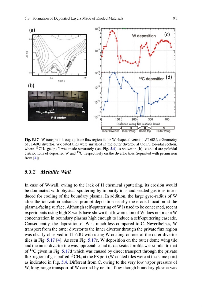
Fig. 5.17 W transport through private flux region in the W-shaped divertor in JT-60U. a Geometry
of JT-60U divertor. W-coated tiles were installed in the outer divertor at the P8 toroidal section,
where 13 CH 4 gas puff was made separately (see Fig. 5.4) as shown in (b). c and d are poloidal
distributions of deposited W and 13 C, respectively on the divertor tiles (reprinted with permission
from [4])
5.3.2 Metallic Wall
In case of W-wall, owing to the lack of H chemical sputtering, its erosion would
be dominated with physical sputtering by impurity ions and seeded gas ions introduced for cooling of the boundary plasma. In addition, the large gyro-radius of W
after the ionization enhances prompt deposition nearby the eroded location at the
plasma-facing surface. Although self-sputtering of W is used to be concerned, recent
experiments using high Z walls have shown that low erosion of W does not make W
concentration in boundary plasma high enough to induce a self-sputtering cascade.
Consequently, the deposition of W is much less compared to C. Nevertheless, W
transport from the outer divertor to the inner divertor through the private flux region
was clearly observed in JT-60U with using W coating on one of the outer divertor
tiles in Fig. 5.17 [4]. As seen Fig. 5.17c, W deposition on the outer dome wing tile
and the inner divertor tile was appreciable and its deposited profile was similar to that
of
13 C given in Fig. 5.17d which was caused by direct transport through the private
flux region of gas puffed
13 CH 4 at the P8 port (W-coated tiles were at the same port)
as indicated in Fig. 5.4. Different from C, owing to the very low vapor pressure of
W, long-range transport of W carried by neutral flow though boundary plasma was
91
Fig. 5.17 W transport through private flux region in the W-shaped divertor in JT-60U. a Geometry
of JT-60U divertor. W-coated tiles were installed in the outer divertor at the P8 toroidal section,
where 13 CH 4 gas puff was made separately (see Fig. 5.4) as shown in (b). c and d are poloidal
distributions of deposited W and 13 C, respectively on the divertor tiles (reprinted with permission
from [4])
5.3.2 Metallic Wall
In case of W-wall, owing to the lack of H chemical sputtering, its erosion would
be dominated with physical sputtering by impurity ions and seeded gas ions introduced for cooling of the boundary plasma. In addition, the large gyro-radius of W
after the ionization enhances prompt deposition nearby the eroded location at the
plasma-facing surface. Although self-sputtering of W is used to be concerned, recent
experiments using high Z walls have shown that low erosion of W does not make W
concentration in boundary plasma high enough to induce a self-sputtering cascade.
Consequently, the deposition of W is much less compared to C. Nevertheless, W
transport from the outer divertor to the inner divertor through the private flux region
was clearly observed in JT-60U with using W coating on one of the outer divertor
tiles in Fig. 5.17 [4]. As seen Fig. 5.17c, W deposition on the outer dome wing tile
and the inner divertor tile was appreciable and its deposited profile was similar to that
of
13 C given in Fig. 5.17d which was caused by direct transport through the private
flux region of gas puffed
13 CH 4 at the P8 port (W-coated tiles were at the same port)
as indicated in Fig. 5.4. Different from C, owing to the very low vapor pressure of
W, long-range transport of W carried by neutral flow though boundary plasma was