

5.3 Formation of Deposited Layers Made of Eroded Materials
89
Bottom eroded
Bottom deposited
Tiles were removed
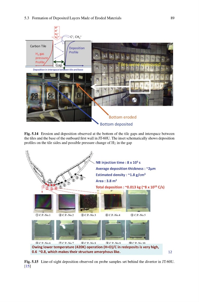
Fig. 5.14 Erosion and deposition observed at the bottom of the tile gaps and interspace between
the tiles and the base of the outboard first wall in JT-60U. The inset schematically shows deposition
profiles on the tile sides and possible pressure change of H 2 in the gap
NB injection time : 8 x 10 3 s
Average deposition thickness : ~2μm
Estimated density : ~1.8 g/cm 3
Area : 3.8 m 2
Total deposition : ~0.013 kg (~8 x 10 19 C/s)
Owing lower temperature (420K) operation (H+D)/C in redeposits is very high,
0.6 ~0.8, which makes their structure amorphous like.
12
Fig. 5.15 Line-of-sight deposition observed on probe samples set behind the divertor in JT-60U.
[15]
89
Bottom eroded
Bottom deposited
Tiles were removed
Fig. 5.14 Erosion and deposition observed at the bottom of the tile gaps and interspace between
the tiles and the base of the outboard first wall in JT-60U. The inset schematically shows deposition
profiles on the tile sides and possible pressure change of H 2 in the gap
NB injection time : 8 x 10 3 s
Average deposition thickness : ~2μm
Estimated density : ~1.8 g/cm 3
Area : 3.8 m 2
Total deposition : ~0.013 kg (~8 x 10 19 C/s)
Owing lower temperature (420K) operation (H+D)/C in redeposits is very high,
0.6 ~0.8, which makes their structure amorphous like.
12
Fig. 5.15 Line-of-sight deposition observed on probe samples set behind the divertor in JT-60U.
[15]