

22
2 Discharges in Current Large Tokamaks
(a)
(b)
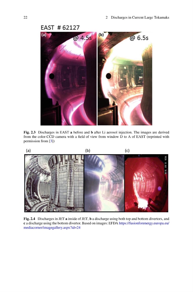
Fig. 2.3 Discharges in EAST a before and b after Li aerosol injection. The images are derived
from the color-CCD camera with a field of view from window D to A of EAST (reprinted with
permission from [3])
(a)
(b)
(c)
Fig. 2.4 Discharges in JET a inside of JET, b a discharge using both top and bottom divertors, and
c a discharge using the bottom divertor. Based on images: EFDA https://fusionforenergy.europa.eu/
mediacorner/imagegallery.aspx?id=24
2 Discharges in Current Large Tokamaks
(a)
(b)
Fig. 2.3 Discharges in EAST a before and b after Li aerosol injection. The images are derived
from the color-CCD camera with a field of view from window D to A of EAST (reprinted with
permission from [3])
(a)
(b)
(c)
Fig. 2.4 Discharges in JET a inside of JET, b a discharge using both top and bottom divertors, and
c a discharge using the bottom divertor. Based on images: EFDA https://fusionforenergy.europa.eu/
mediacorner/imagegallery.aspx?id=24