

9.4 Fuel Retention in Carbon Materials
167
Graphite grain
Graphite tile
Plasma
D + ,T +
H +
Isotopic
replacement by H
D(T) retention
H 2
D 2 (DT)
DD discharge
HH discharge
On grain surfaces facing to
open pores (inner surface)
H, D, T retention
Bulk
deeper
10 -1
10 0
10 1
10 2
10 3
Depth from the plasma facing surface [µm]
shallow region
H
D
T(x10 6 )
10 4
Plasma facing surface
Background level of H
Isotope replacement Direct
injection
Retention on inner surface
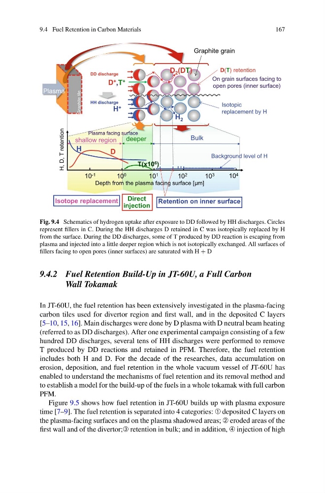
Fig. 9.4 Schematics of hydrogen uptake after exposure to DD followed by HH discharges. Circles
represent fillers in C. During the HH discharges D retained in C was isotopically replaced by H
from the surface. During the DD discharges, some of T produced by DD reaction is escaping from
plasma and injected into a little deeper region which is not isotopically exchanged. All surfaces of
fillers facing to open pores (inner surfaces) are saturated with H + D
9.4.2 Fuel Retention Build-Up in JT-60U, a Full Carbon
Wall Tokamak
In JT-60U, the fuel retention has been extensively investigated in the plasma-facing
carbon tiles used for divertor region and first wall, and in the deposited C layers
[5–10, 15, 16]. Main discharges were done by D plasma with D neutral beam heating
(referred to as DD discharges). After one experimental campaign consisting of a few
hundred DD discharges, several tens of HH discharges were performed to remove
T produced by DD reactions and retained in PFM. Therefore, the fuel retention
includes both H and D. For the decade of the researches, data accumulation on
erosion, deposition, and fuel retention in the whole vacuum vessel of JT-60U has
enabled to understand the mechanisms of fuel retention and its removal method and
to establish a model for the build-up of the fuels in a whole tokamak with full carbon
PFM.
Figure 9.5 shows how fuel retention in JT-60U builds up with plasma exposure
time [7–9]. The fuel retention is separated into 4 categories: ➀ deposited C layers on
the plasma-facing surfaces and on the plasma shadowed areas; ➁ eroded areas of the
first wall and of the divertor;➂ retention in bulk; and in addition, ➃ injection of high
167
Graphite grain
Graphite tile
Plasma
D + ,T +
H +
Isotopic
replacement by H
D(T) retention
H 2
D 2 (DT)
DD discharge
HH discharge
On grain surfaces facing to
open pores (inner surface)
H, D, T retention
Bulk
deeper
10 -1
10 0
10 1
10 2
10 3
Depth from the plasma facing surface [µm]
shallow region
H
D
T(x10 6 )
10 4
Plasma facing surface
Background level of H
Isotope replacement Direct
injection
Retention on inner surface
Fig. 9.4 Schematics of hydrogen uptake after exposure to DD followed by HH discharges. Circles
represent fillers in C. During the HH discharges D retained in C was isotopically replaced by H
from the surface. During the DD discharges, some of T produced by DD reaction is escaping from
plasma and injected into a little deeper region which is not isotopically exchanged. All surfaces of
fillers facing to open pores (inner surfaces) are saturated with H + D
9.4.2 Fuel Retention Build-Up in JT-60U, a Full Carbon
Wall Tokamak
In JT-60U, the fuel retention has been extensively investigated in the plasma-facing
carbon tiles used for divertor region and first wall, and in the deposited C layers
[5–10, 15, 16]. Main discharges were done by D plasma with D neutral beam heating
(referred to as DD discharges). After one experimental campaign consisting of a few
hundred DD discharges, several tens of HH discharges were performed to remove
T produced by DD reactions and retained in PFM. Therefore, the fuel retention
includes both H and D. For the decade of the researches, data accumulation on
erosion, deposition, and fuel retention in the whole vacuum vessel of JT-60U has
enabled to understand the mechanisms of fuel retention and its removal method and
to establish a model for the build-up of the fuels in a whole tokamak with full carbon
PFM.
Figure 9.5 shows how fuel retention in JT-60U builds up with plasma exposure
time [7–9]. The fuel retention is separated into 4 categories: ➀ deposited C layers on
the plasma-facing surfaces and on the plasma shadowed areas; ➁ eroded areas of the
first wall and of the divertor;➂ retention in bulk; and in addition, ➃ injection of high