

494
B. Arizmendi et al.
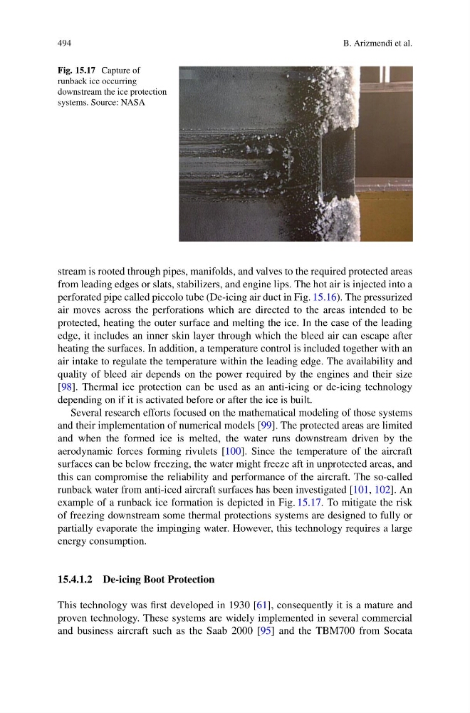
Fig. 15.17 Capture of
runback ice occurring
downstream the ice protection
systems. Source: NASA
stream is rooted through pipes, manifolds, and valves to the required protected areas
from leading edges or slats, stabilizers, and engine lips. The hot air is injected into a
perforated pipe called piccolo tube (De-icing air duct in Fig. 15.16). The pressurized
air moves across the perforations which are directed to the areas intended to be
protected, heating the outer surface and melting the ice. In the case of the leading
edge, it includes an inner skin layer through which the bleed air can escape after
heating the surfaces. In addition, a temperature control is included together with an
air intake to regulate the temperature within the leading edge. The availability and
quality of bleed air depends on the power required by the engines and their size
[98]. Thermal ice protection can be used as an anti-icing or de-icing technology
depending on if it is activated before or after the ice is built.
Several research efforts focused on the mathematical modeling of those systems
and their implementation of numerical models [99]. The protected areas are limited
and when the formed ice is melted, the water runs downstream driven by the
aerodynamic forces forming rivulets [100]. Since the temperature of the aircraft
surfaces can be below freezing, the water might freeze aft in unprotected areas, and
this can compromise the reliability and performance of the aircraft. The so-called
runback water from anti-iced aircraft surfaces has been investigated [101, 102]. An
example of a runback ice formation is depicted in Fig. 15.17. To mitigate the risk
of freezing downstream some thermal protections systems are designed to fully or
partially evaporate the impinging water. However, this technology requires a large
energy consumption.
15.4.1.2 De-icing Boot Protection
This technology was first developed in 1930 [61], consequently it is a mature and
proven technology. These systems are widely implemented in several commercial
and business aircraft such as the Saab 2000 [95] and the TBM700 from Socata
B. Arizmendi et al.
Fig. 15.17 Capture of
runback ice occurring
downstream the ice protection
systems. Source: NASA
stream is rooted through pipes, manifolds, and valves to the required protected areas
from leading edges or slats, stabilizers, and engine lips. The hot air is injected into a
perforated pipe called piccolo tube (De-icing air duct in Fig. 15.16). The pressurized
air moves across the perforations which are directed to the areas intended to be
protected, heating the outer surface and melting the ice. In the case of the leading
edge, it includes an inner skin layer through which the bleed air can escape after
heating the surfaces. In addition, a temperature control is included together with an
air intake to regulate the temperature within the leading edge. The availability and
quality of bleed air depends on the power required by the engines and their size
[98]. Thermal ice protection can be used as an anti-icing or de-icing technology
depending on if it is activated before or after the ice is built.
Several research efforts focused on the mathematical modeling of those systems
and their implementation of numerical models [99]. The protected areas are limited
and when the formed ice is melted, the water runs downstream driven by the
aerodynamic forces forming rivulets [100]. Since the temperature of the aircraft
surfaces can be below freezing, the water might freeze aft in unprotected areas, and
this can compromise the reliability and performance of the aircraft. The so-called
runback water from anti-iced aircraft surfaces has been investigated [101, 102]. An
example of a runback ice formation is depicted in Fig. 15.17. To mitigate the risk
of freezing downstream some thermal protections systems are designed to fully or
partially evaporate the impinging water. However, this technology requires a large
energy consumption.
15.4.1.2 De-icing Boot Protection
This technology was first developed in 1930 [61], consequently it is a mature and
proven technology. These systems are widely implemented in several commercial
and business aircraft such as the Saab 2000 [95] and the TBM700 from Socata