

442
C. Sabater
Design Vector
Obtain new
Geometry
Obtain surface mesh
node displacements
w.r.t. Baseline
Deformed Mesh
Apply BC
(Mach, )
Store
Flowfield
MESH DEFORMATION
PREPROCESSING
SOLVER
POSTPROCESSING
Convert to
Tecplot
TAU Solver
TAU SoluƟon
Drag Coefficient
Deformed Mesh
TAU Solver
TAU SoluƟon
Apply Mesh
DeformaƟon
Run TAU
Preprocessor
Obtain Surface
SoluƟon
Run TAU
Flow Solver
Fig. 14.3 CFD Process Chain used to evaluate the drag coefficient for a given design vector and
operating conditions
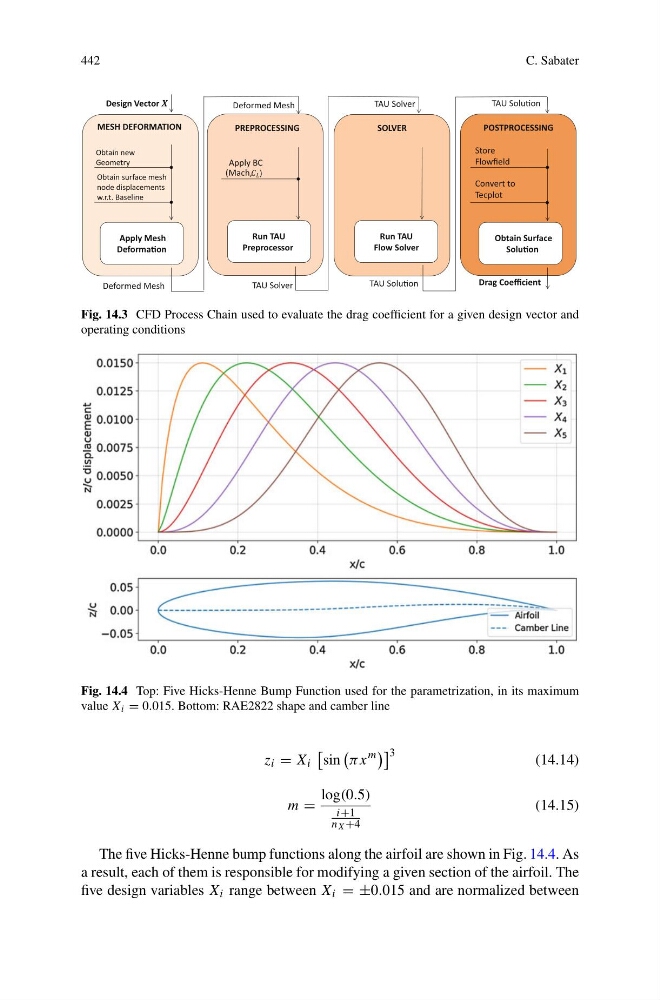
Fig. 14.4 Top: Five Hicks-Henne Bump Function used for the parametrization, in its maximum
value X i = 0.015. Bottom: RAE2822 shape and camber line
z i = X i
sin
πx
m
3
(14.14)
m =
log(0.5)
i+1
n X +4
(14.15)
The five Hicks-Henne bump functions along the airfoil are shown in Fig. 14.4. As
a result, each of them is responsible for modifying a given section of the airfoil. The
five design variables X i range between X i = ±0.015 and are normalized between
C. Sabater
Design Vector
Obtain new
Geometry
Obtain surface mesh
node displacements
w.r.t. Baseline
Deformed Mesh
Apply BC
(Mach, )
Store
Flowfield
MESH DEFORMATION
PREPROCESSING
SOLVER
POSTPROCESSING
Convert to
Tecplot
TAU Solver
TAU SoluƟon
Drag Coefficient
Deformed Mesh
TAU Solver
TAU SoluƟon
Apply Mesh
DeformaƟon
Run TAU
Preprocessor
Obtain Surface
SoluƟon
Run TAU
Flow Solver
Fig. 14.3 CFD Process Chain used to evaluate the drag coefficient for a given design vector and
operating conditions
Fig. 14.4 Top: Five Hicks-Henne Bump Function used for the parametrization, in its maximum
value X i = 0.015. Bottom: RAE2822 shape and camber line
z i = X i
sin
πx
m
3
(14.14)
m =
log(0.5)
i+1
n X +4
(14.15)
The five Hicks-Henne bump functions along the airfoil are shown in Fig. 14.4. As
a result, each of them is responsible for modifying a given section of the airfoil. The
five design variables X i range between X i = ±0.015 and are normalized between