

14 Best Practices for Surrogate Based Uncertainty Quantification in. . .
441
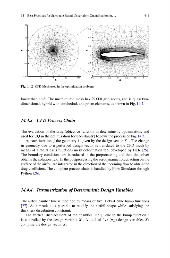
Fig. 14.2 CFD Mesh used in the optimization problem
lower than 1e-8. The unstructured mesh has 29,000 grid nodes, and is quasi twodimensional, hybrid with tetrahedral, and prism elements, as shown in Fig. 14.2.
14.4.3 CFD Process Chain
The evaluation of the drag (objective function in deterministic optimization, and
used for UQ in the optimization for uncertainty) follows the process of Fig. 14.3.
At each iteration j the geometry is given by the design vector X j . The change
in geometry due to a perturbed design vector is translated to the CFD mesh by
means of a radial basis functions mesh deformation tool developed by DLR [25].
The boundary conditions are introduced in the preprocessing and then the solver
obtains the solution field. In the postprocessing the aerodynamic forces acting on the
surface of the airfoil are integrated in the direction of the incoming flow to obtain the
drag coefficient. The complete process chain is handled by Flow Simulator through
Python [26].
14.4.4 Parametrization of Deterministic Design Variables
The airfoil camber line is modified by means of five Hicks-Henne bump functions
[27]. As a result it is possible to modify the airfoil shape while satisfying the
thickness distribution constraint.
The vertical displacement of the chamber line z i due to the bump function i
is controlled by the design variable X i . A total of five (n X ) design variables X i
compose the design vector X.
441
Fig. 14.2 CFD Mesh used in the optimization problem
lower than 1e-8. The unstructured mesh has 29,000 grid nodes, and is quasi twodimensional, hybrid with tetrahedral, and prism elements, as shown in Fig. 14.2.
14.4.3 CFD Process Chain
The evaluation of the drag (objective function in deterministic optimization, and
used for UQ in the optimization for uncertainty) follows the process of Fig. 14.3.
At each iteration j the geometry is given by the design vector X j . The change
in geometry due to a perturbed design vector is translated to the CFD mesh by
means of a radial basis functions mesh deformation tool developed by DLR [25].
The boundary conditions are introduced in the preprocessing and then the solver
obtains the solution field. In the postprocessing the aerodynamic forces acting on the
surface of the airfoil are integrated in the direction of the incoming flow to obtain the
drag coefficient. The complete process chain is handled by Flow Simulator through
Python [26].
14.4.4 Parametrization of Deterministic Design Variables
The airfoil camber line is modified by means of five Hicks-Henne bump functions
[27]. As a result it is possible to modify the airfoil shape while satisfying the
thickness distribution constraint.
The vertical displacement of the chamber line z i due to the bump function i
is controlled by the design variable X i . A total of five (n X ) design variables X i
compose the design vector X.