

350
L. Gentile et al.
back to the optimizer. Nevertheless, to simulate the uncertainty, the nominal
lamination angles and loads magnitudes are perturbed randomly by Gaussian
perturbations with mean 0 and variance, respectively, 1 and 0.1. The candidates
and the function responses are used to train a Kriging model. Then, an optimizer
searches for the most promising candidate solution by optimizing an infill criterion
based on the model. Here, the criterion is the expected improvement. Based on the
assumption of expensive function evaluations, a very small budget of 150 function
evaluations has been used.
10.5.4 Results
The obtained results clearly highlight that mixed-discrete problems present peculiar
challenges. Such issues are unlikely to be resolved by continuous optimizers. A
convergence plot is shown in Fig. 10.5. It can be seen that the best configuration
found by MIES outperforms the one found by DE. Although the processes have
been started from the same design, the results differ by around 80% (Table 10.2).
However, to have a statistically meaningful comparison, we should repeat the
analyses with the two best designs in order to quantify the effect of the uncertainties.
The displacements of the two best plate configurations are shown in Fig. 10.3
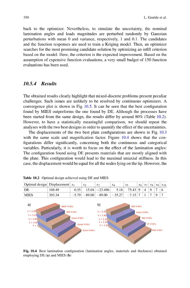
with the same scale and magnification factor. Figure 10.4 shows that the configurations differ significantly, concerning both the continuous and categorical
variables. Particularly, it is worth to focus on the effect of the lamination angles:
The configuration found using DE presents materials that are mostly aligned with
the plate. This configuration would lead to the maximal uniaxial stiffness. In this
case, the displacement would be equal for all the nodes lying on the tip. However, the
Table 10.2 Optimal design achieved using DE and MIES
Optimal design Displacement x 1
x 2
x 3
x 4
x 5
x 6 x 7 x 8 x 9 x 10
DE
169.49
0.35 15.04 −23.496
5.18 75.43 9 4 9 7 6
MIES
303.34
−5.79 −89.00 −89.00 −35.27 −7.15 7 1 7 9 7
Fig. 10.4 Best lamination configuration (lamination angles, materials and thickness) obtained
employing DE (a) and MIES (b)
L. Gentile et al.
back to the optimizer. Nevertheless, to simulate the uncertainty, the nominal
lamination angles and loads magnitudes are perturbed randomly by Gaussian
perturbations with mean 0 and variance, respectively, 1 and 0.1. The candidates
and the function responses are used to train a Kriging model. Then, an optimizer
searches for the most promising candidate solution by optimizing an infill criterion
based on the model. Here, the criterion is the expected improvement. Based on the
assumption of expensive function evaluations, a very small budget of 150 function
evaluations has been used.
10.5.4 Results
The obtained results clearly highlight that mixed-discrete problems present peculiar
challenges. Such issues are unlikely to be resolved by continuous optimizers. A
convergence plot is shown in Fig. 10.5. It can be seen that the best configuration
found by MIES outperforms the one found by DE. Although the processes have
been started from the same design, the results differ by around 80% (Table 10.2).
However, to have a statistically meaningful comparison, we should repeat the
analyses with the two best designs in order to quantify the effect of the uncertainties.
The displacements of the two best plate configurations are shown in Fig. 10.3
with the same scale and magnification factor. Figure 10.4 shows that the configurations differ significantly, concerning both the continuous and categorical
variables. Particularly, it is worth to focus on the effect of the lamination angles:
The configuration found using DE presents materials that are mostly aligned with
the plate. This configuration would lead to the maximal uniaxial stiffness. In this
case, the displacement would be equal for all the nodes lying on the tip. However, the
Table 10.2 Optimal design achieved using DE and MIES
Optimal design Displacement x 1
x 2
x 3
x 4
x 5
x 6 x 7 x 8 x 9 x 10
DE
169.49
0.35 15.04 −23.496
5.18 75.43 9 4 9 7 6
MIES
303.34
−5.79 −89.00 −89.00 −35.27 −7.15 7 1 7 9 7
Fig. 10.4 Best lamination configuration (lamination angles, materials and thickness) obtained
employing DE (a) and MIES (b)