

32 Techno-Economic Analysis of a Hybrid Solar-Hydrogen-Biomass …
489
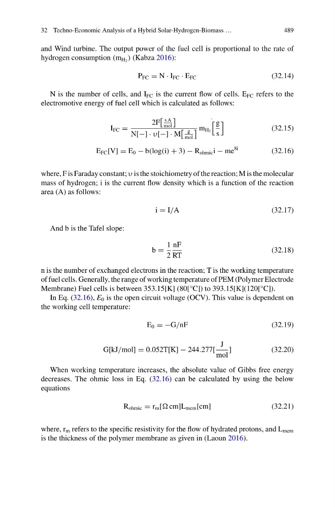
and Wind turbine. The output power of the fuel cell is proportional to the rate of
hydrogen consumption (m H 2 ) (Kabza 2016):
P FC = N · I FC · E FC
(32.14)
N is the number of cells, and I FC is the current flow of cells. E FC refers to the
electromotive energy of fuel cell which is calculated as follows:
I FC =
2F
s A
mol
N[−] · υ[−] · M
g
mol
·
m H 2
g
s
(32.15)
E FC [V] = E 0 − b(log(i) + 3) − R ohmic i − me
8i
(32.16)
where, F is Faraday constant; υ is the stoichiometry of the reaction; M is the molecular
mass of hydrogen; i is the current flow density which is a function of the reaction
area (A) as follows:
i = I/A
(32.17)
And b is the Tafel slope:
b =
1
2
nF
RT
(32.18)
n is the number of exchanged electrons in the reaction; T is the working temperature
of fuel cells. Generally, the range of working temperature of PEM (Polymer Electrode
Membrane) Fuel cells is between 353.15[K] (80[°C]) to 393.15[K](120[°C]).
In Eq. (32.16), E 0 is the open circuit voltage (OCV). This value is dependent on
the working cell temperature:
E 0 = −G/nF
(32.19)
G[kJ/mol] = 0.052T[K] − 244.277[
J
mol
]
(32.20)
When working temperature increases, the absolute value of Gibbs free energy
decreases. The ohmic loss in Eq. (32.16) can be calculated by using the below
equations
R ohmic = r m [ cm]L mem [cm]
(32.21)
where, r m refers to the specific resistivity for the flow of hydrated protons, and L mem
is the thickness of the polymer membrane as given in (Laoun 2016).
489
and Wind turbine. The output power of the fuel cell is proportional to the rate of
hydrogen consumption (m H 2 ) (Kabza 2016):
P FC = N · I FC · E FC
(32.14)
N is the number of cells, and I FC is the current flow of cells. E FC refers to the
electromotive energy of fuel cell which is calculated as follows:
I FC =
2F
s A
mol
N[−] · υ[−] · M
g
mol
·
m H 2
g
s
(32.15)
E FC [V] = E 0 − b(log(i) + 3) − R ohmic i − me
8i
(32.16)
where, F is Faraday constant; υ is the stoichiometry of the reaction; M is the molecular
mass of hydrogen; i is the current flow density which is a function of the reaction
area (A) as follows:
i = I/A
(32.17)
And b is the Tafel slope:
b =
1
2
nF
RT
(32.18)
n is the number of exchanged electrons in the reaction; T is the working temperature
of fuel cells. Generally, the range of working temperature of PEM (Polymer Electrode
Membrane) Fuel cells is between 353.15[K] (80[°C]) to 393.15[K](120[°C]).
In Eq. (32.16), E 0 is the open circuit voltage (OCV). This value is dependent on
the working cell temperature:
E 0 = −G/nF
(32.19)
G[kJ/mol] = 0.052T[K] − 244.277[
J
mol
]
(32.20)
When working temperature increases, the absolute value of Gibbs free energy
decreases. The ohmic loss in Eq. (32.16) can be calculated by using the below
equations
R ohmic = r m [ cm]L mem [cm]
(32.21)
where, r m refers to the specific resistivity for the flow of hydrated protons, and L mem
is the thickness of the polymer membrane as given in (Laoun 2016).