

5.7 Design of Ground Test System
379
Table 5.4 Numerical experiment Conditions of determining spacecraft’s attitude parameters based
on X-ray pulsars
Number Name of indicator
Value of indicator Notes
1
Accuracy of pulsar’s angular
position (×10 −3 arc-second)
0.1
2
Number of tracking pulsars at
the same time
2
3
Accuracy of measuring pulsar’s
direction vector (arc-second)
10, 100
Constructing ten experimental
examples
4
Sampling interval of detector’s
data (s)
5, 10, 50, 100, 500
5
Constant drift of gyroscope
(°/h)
3
Only considering the constant
drift and measurement random
white noise of gyroscope
6
Measurement noise variance of
gyroscope (°/h 1/2 )
0.05
7
Data updating frequency of
gyroscope (Hz)
20
8
Time span of numerical
experiment (hour)
24
Table 5.5 Estimation accuracies of attitude parameters of spacecraft based on X-ray pulsars
Accuracy of attitude
angles
Yaw (as)
Pitch (as)
Roll (as)
Example number
Direction vector
accuracy & sampling
interval
10as
5 s
0.73
0.41
0.75
T01
10 s
1.40
0.69
1.43
T02
50 s
3.86
2.53
3.95
T03
100 s
6.60
4.60
6.63
T04
500 s
16.93
11.80
20.40
T05
100as
5 s
1.24
0.82
1.46
T06
10 s
2.14
1.44
2.36
T07
50 s
7.14
5.62
7.64
T08
100 s
16.60
8.30
16.39
T09
500 s
48.99
37.87
59.47
T10
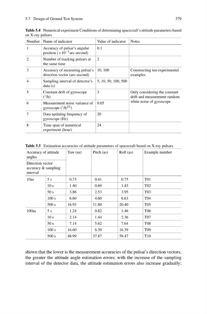
shown that the lower is the measurement accuracies of the pulsar’s direction vectors,
the greater the attitude angle estimation errors; with the increase of the sampling
interval of the detector data, the attitude estimation errors also increase gradually;
379
Table 5.4 Numerical experiment Conditions of determining spacecraft’s attitude parameters based
on X-ray pulsars
Number Name of indicator
Value of indicator Notes
1
Accuracy of pulsar’s angular
position (×10 −3 arc-second)
0.1
2
Number of tracking pulsars at
the same time
2
3
Accuracy of measuring pulsar’s
direction vector (arc-second)
10, 100
Constructing ten experimental
examples
4
Sampling interval of detector’s
data (s)
5, 10, 50, 100, 500
5
Constant drift of gyroscope
(°/h)
3
Only considering the constant
drift and measurement random
white noise of gyroscope
6
Measurement noise variance of
gyroscope (°/h 1/2 )
0.05
7
Data updating frequency of
gyroscope (Hz)
20
8
Time span of numerical
experiment (hour)
24
Table 5.5 Estimation accuracies of attitude parameters of spacecraft based on X-ray pulsars
Accuracy of attitude
angles
Yaw (as)
Pitch (as)
Roll (as)
Example number
Direction vector
accuracy & sampling
interval
10as
5 s
0.73
0.41
0.75
T01
10 s
1.40
0.69
1.43
T02
50 s
3.86
2.53
3.95
T03
100 s
6.60
4.60
6.63
T04
500 s
16.93
11.80
20.40
T05
100as
5 s
1.24
0.82
1.46
T06
10 s
2.14
1.44
2.36
T07
50 s
7.14
5.62
7.64
T08
100 s
16.60
8.30
16.39
T09
500 s
48.99
37.87
59.47
T10
shown that the lower is the measurement accuracies of the pulsar’s direction vectors,
the greater the attitude angle estimation errors; with the increase of the sampling
interval of the detector data, the attitude estimation errors also increase gradually;