

5.4. CARBON NANOTUBES
1 17
The mechanism of nanotube growth is not understood. Since the metal catalyst is
necessary for the growth of SWNTs, the mechanism must involve the role of the Co
or Ni atoms. One proposal referred to as the “scootter mechanism” suggests that
atoms of the metal catalyst attach to the dangling bonds at the open end of the tubes,
and that these atoms scoot around the rim of the tube, absorbing carbon atoms as
they arrive.
Generally when nanotubes are synthesized, the result is a mix of different kinds,
some metallic and some semiconducting. A group at IBM has developed a method
to separate the semiconducting from the metallic nanotubes. The separation was
accomplished by depositing bundles of nanotubes, some of which are metallic and
some semiconducting, on a silicon wafer. Metal electrodes were then deposited over
the bundle. Using the silicon wafer as an electrode, a small bias voltage was applied
that prevents the semiconducting tubes from conducting, effectively making them
insulators. A high voltage is then applied across the metal electrodes, thereby
sending a high current through the metallic tubes but not the insulating tubes. This
causes the metallic tubes to vaporize, leaving behind only the semiconducting tubes.
5.4.2. Structure
There are a variety of structures of carbon nanotubes, and these various structures
have different properties. Although carbon nanotubes are not actually made by
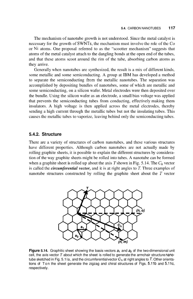
rolling graphite sheets, it is possible to explain the different structures by consideration of the way graphite sheets might be rolled into tubes. A nanotube can be formed
when a graphite sheet is rolled up about the axis T shown in Fig. 5.14. The C , vector
is called the circumferential vector, and it is at right angles to T Three examples of
nanotube structures constructed by rolling the graphite sheet about the T vector
T
Figure 5.14. Graphitic sheet showing the basis vectors a, and a2 of the two-dimensional unit
cell, the axis vector T about which the sheet is rolled to generate the armchair structure nanotube sketched in Fig. 5.1 la, and the circumferential vector Ch at right angles to T. Other orientations of T o n the sheet generate the zigzag and chiral structures of Figs. 5.11b and 5.11c,
respectively.
1 17
The mechanism of nanotube growth is not understood. Since the metal catalyst is
necessary for the growth of SWNTs, the mechanism must involve the role of the Co
or Ni atoms. One proposal referred to as the “scootter mechanism” suggests that
atoms of the metal catalyst attach to the dangling bonds at the open end of the tubes,
and that these atoms scoot around the rim of the tube, absorbing carbon atoms as
they arrive.
Generally when nanotubes are synthesized, the result is a mix of different kinds,
some metallic and some semiconducting. A group at IBM has developed a method
to separate the semiconducting from the metallic nanotubes. The separation was
accomplished by depositing bundles of nanotubes, some of which are metallic and
some semiconducting, on a silicon wafer. Metal electrodes were then deposited over
the bundle. Using the silicon wafer as an electrode, a small bias voltage was applied
that prevents the semiconducting tubes from conducting, effectively making them
insulators. A high voltage is then applied across the metal electrodes, thereby
sending a high current through the metallic tubes but not the insulating tubes. This
causes the metallic tubes to vaporize, leaving behind only the semiconducting tubes.
5.4.2. Structure
There are a variety of structures of carbon nanotubes, and these various structures
have different properties. Although carbon nanotubes are not actually made by
rolling graphite sheets, it is possible to explain the different structures by consideration of the way graphite sheets might be rolled into tubes. A nanotube can be formed
when a graphite sheet is rolled up about the axis T shown in Fig. 5.14. The C , vector
is called the circumferential vector, and it is at right angles to T Three examples of
nanotube structures constructed by rolling the graphite sheet about the T vector
T
Figure 5.14. Graphitic sheet showing the basis vectors a, and a2 of the two-dimensional unit
cell, the axis vector T about which the sheet is rolled to generate the armchair structure nanotube sketched in Fig. 5.1 la, and the circumferential vector Ch at right angles to T. Other orientations of T o n the sheet generate the zigzag and chiral structures of Figs. 5.11b and 5.11c,
respectively.