

116
CARBON NANOSTRUCTURES
FURNACE
I
I
WATER COOLED
I
COPPER COLLECTOR
LASER
I
I
I
I
I
I
I
I
I
I
\
I
I
I
I
I
ARGON GAS
I
\
\
\
\
\
GRAPHITE TARGET
,
QUARTZ TUBE
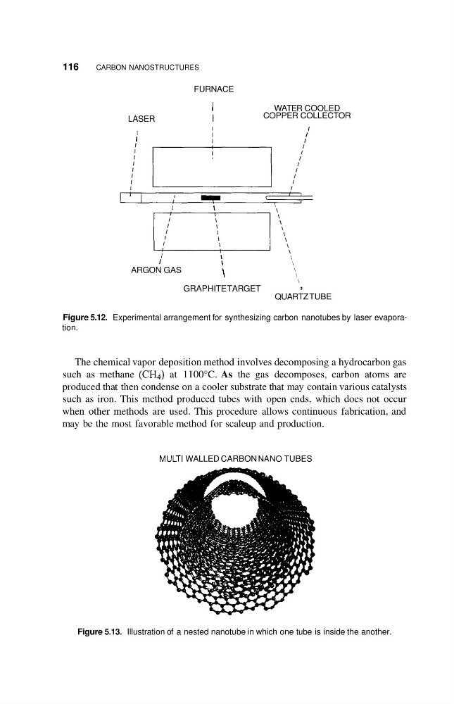
Figure 5.12. Experimental arrangement for synthesizing carbon nanotubes by laser evaporation.
The chemical vapor deposition method involves decomposing a hydrocarbon gas
such as methane (CH4) at 1100°C. As the gas decomposes, carbon atoms are
produced that then condense on a cooler substrate that may contain various catalysts
such as iron. This method produced tubes with open ends, which does not occur
when other methods are used. This procedure allows continuous fabrication, and
may be the most favorable method for scaleup and production.
MULTI WALLED CARBON NAN0 TUBES
Figure 5.13. Illustration of a nested nanotube in which one tube is inside the another.
CARBON NANOSTRUCTURES
FURNACE
I
I
WATER COOLED
I
COPPER COLLECTOR
LASER
I
I
I
I
I
I
I
I
I
I
\
I
I
I
I
I
ARGON GAS
I
\
\
\
\
\
GRAPHITE TARGET
,
QUARTZ TUBE
Figure 5.12. Experimental arrangement for synthesizing carbon nanotubes by laser evaporation.
The chemical vapor deposition method involves decomposing a hydrocarbon gas
such as methane (CH4) at 1100°C. As the gas decomposes, carbon atoms are
produced that then condense on a cooler substrate that may contain various catalysts
such as iron. This method produced tubes with open ends, which does not occur
when other methods are used. This procedure allows continuous fabrication, and
may be the most favorable method for scaleup and production.
MULTI WALLED CARBON NAN0 TUBES
Figure 5.13. Illustration of a nested nanotube in which one tube is inside the another.