

E1C12 09/14/2010
13:54:15 Page 555
In the previous example, the response for a damping ratio of 0.7 appears to be the most likely
candidate to meet our needs. But can we improve the situation by implementing a controller?
Proportional Control
Consider the application of a proportional controller to the second-order system described in
Example 12.7 for the case where the damping coefficient is 0.3. The block diagram for the control
system is shown in Figure 12.58.
The transfer function for this system when the damping ratio is 0.3 is
Y s
ð Þ
KF s
ð Þ
¼
k p
1
v 2
n
s
2
þ
2z
v n
s þ 1
2
6
6
4
3
7
7
5 ¼
k p
1
3950
s
2
þ 0:02235s þ 1
2
6
4
3
7
5
ð12:63Þ
We implement a proportional controller having a proportional gain of 10, and examine the
step response of the system. Figure 12.59 shows the resulting response of the system. Clearly, we
have not eliminated the overshoot and oscillations in this system. On the other hand, if we
implement the same controller for the system having a damping ratio of 1.3, the response is shown
in Figure 12.60. Here the proportional controller is helpful for the performance of the system. Let’s
explore whether a more sophisticated control scheme improves the response of the system having a
damping ratio of 0.3.
0
0.1
0.2
0.3
0.4
0.5
0.6
0.7
0.8
0.9
1
0.2
0.18
0.16
0.14
0.12
0.1
0.08
0.06
0.04
0.02
0
Time (s)
Step response
Amplitude
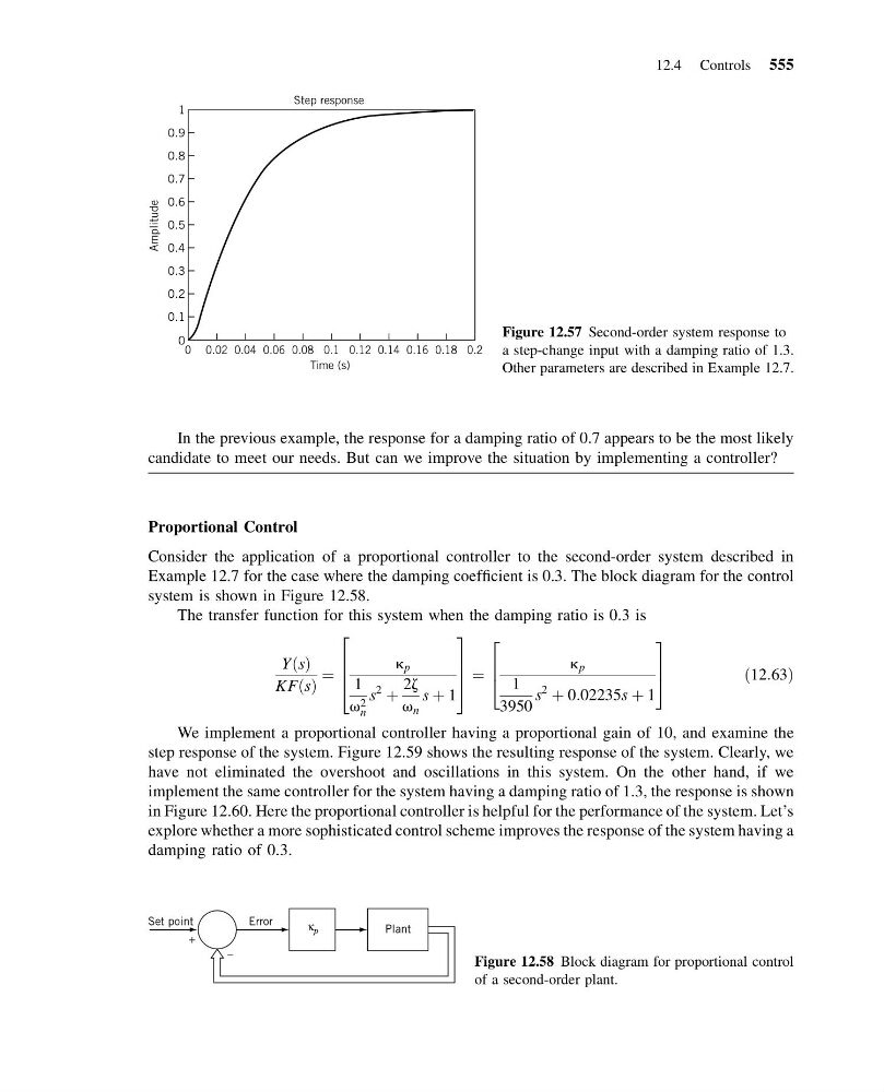
Figure 12.57 Second-order system response to
a step-change input with a damping ratio of 1.3.
Other parameters are described in Example 12.7.
+
–
Plant
Error
Set point
κ p
Figure 12.58 Block diagram for proportional control
of a second-order plant.
12.4 Controls 555
13:54:15 Page 555
In the previous example, the response for a damping ratio of 0.7 appears to be the most likely
candidate to meet our needs. But can we improve the situation by implementing a controller?
Proportional Control
Consider the application of a proportional controller to the second-order system described in
Example 12.7 for the case where the damping coefficient is 0.3. The block diagram for the control
system is shown in Figure 12.58.
The transfer function for this system when the damping ratio is 0.3 is
Y s
ð Þ
KF s
ð Þ
¼
k p
1
v 2
n
s
2
þ
2z
v n
s þ 1
2
6
6
4
3
7
7
5 ¼
k p
1
3950
s
2
þ 0:02235s þ 1
2
6
4
3
7
5
ð12:63Þ
We implement a proportional controller having a proportional gain of 10, and examine the
step response of the system. Figure 12.59 shows the resulting response of the system. Clearly, we
have not eliminated the overshoot and oscillations in this system. On the other hand, if we
implement the same controller for the system having a damping ratio of 1.3, the response is shown
in Figure 12.60. Here the proportional controller is helpful for the performance of the system. Let’s
explore whether a more sophisticated control scheme improves the response of the system having a
damping ratio of 0.3.
0
0.1
0.2
0.3
0.4
0.5
0.6
0.7
0.8
0.9
1
0.2
0.18
0.16
0.14
0.12
0.1
0.08
0.06
0.04
0.02
0
Time (s)
Step response
Amplitude
Figure 12.57 Second-order system response to
a step-change input with a damping ratio of 1.3.
Other parameters are described in Example 12.7.
+
–
Plant
Error
Set point
κ p
Figure 12.58 Block diagram for proportional control
of a second-order plant.
12.4 Controls 555