

E1C12 09/14/2010
13:54:15 Page 552
Once again we impose a step change in the set-point temperature so that Q set s
ð Þ ¼
u 1
s
, and
Q s
ð Þ ¼
u 1 k m k p s þ k I
À
Á C 2
Â
Ã
s C 1 s 2 þ s 1 þ C 2 k m k p
À
Á þ C 2 k m k I
Â
Ã
ð12:55Þ
Employing the final value theorem, we multiply by s and take the limit as s ! 0
lim
s!0 Q s
ð Þ ¼
lim
s!0
s k m k p s þ k I
À
Á C 2
Â
Ã
u 1
s C 1 s 2 þ s 1 þ C 2 k m k p
À
Á þ C 2 k m k I
Â
à ¼
C 2 k m k I
C 2 k m k I
u 1 ¼ u 1
ð12:56Þ
Clearly, the steady-state error for this PI controller is zero. This is a general result for PI control.
Time Response
The time response of this system to a step-change input could be determined by finding the inverse
Laplace transform of Equation 12.57:
Q s
ð Þ
Q set s
ð Þ
¼
k m k p s þ k I
À
Á C 2
C 1 s 2 þ s 1 þ C 2 k m k p
À
Á þ C 2 k m k I
ð12:57Þ
However, by comparison with the Laplace transform of the governing differential equation for a
second-order system, as provided in Equation 3.13, Palm (7) shows that
B ¼
1 þ C 2 k m k p
2
ffiffiffiffiffiffiffiffiffiffiffiffiffiffiffiffiffiffiffiffi ffi
C 1 C 2 k m k I
p
ð12:58Þ
and that for B < 1 the equivalent time constant is
t ¼
2C 1
1 þ C 2 k m k p
ð12:59Þ
The behavior of the oven-controller system can be further explored using the program file First
Order PID.vi.
Q loss
E
Θ set
Θ set
– Θ
Θ
Θ
P
+
–
κ m
κ I
s
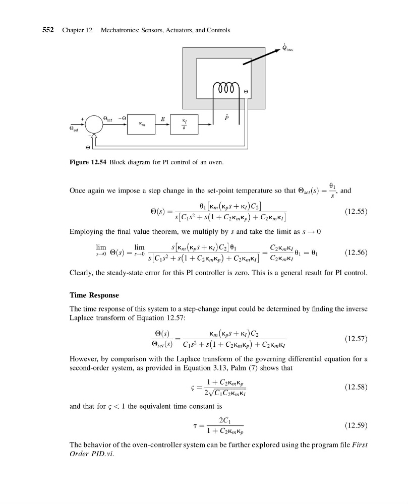
Figure 12.54 Block diagram for PI control of an oven.
552 Chapter 12 Mechatronics: Sensors, Actuators, and Controls
13:54:15 Page 552
Once again we impose a step change in the set-point temperature so that Q set s
ð Þ ¼
u 1
s
, and
Q s
ð Þ ¼
u 1 k m k p s þ k I
À
Á C 2
Â
Ã
s C 1 s 2 þ s 1 þ C 2 k m k p
À
Á þ C 2 k m k I
Â
Ã
ð12:55Þ
Employing the final value theorem, we multiply by s and take the limit as s ! 0
lim
s!0 Q s
ð Þ ¼
lim
s!0
s k m k p s þ k I
À
Á C 2
Â
Ã
u 1
s C 1 s 2 þ s 1 þ C 2 k m k p
À
Á þ C 2 k m k I
Â
à ¼
C 2 k m k I
C 2 k m k I
u 1 ¼ u 1
ð12:56Þ
Clearly, the steady-state error for this PI controller is zero. This is a general result for PI control.
Time Response
The time response of this system to a step-change input could be determined by finding the inverse
Laplace transform of Equation 12.57:
Q s
ð Þ
Q set s
ð Þ
¼
k m k p s þ k I
À
Á C 2
C 1 s 2 þ s 1 þ C 2 k m k p
À
Á þ C 2 k m k I
ð12:57Þ
However, by comparison with the Laplace transform of the governing differential equation for a
second-order system, as provided in Equation 3.13, Palm (7) shows that
B ¼
1 þ C 2 k m k p
2
ffiffiffiffiffiffiffiffiffiffiffiffiffiffiffiffiffiffiffiffi ffi
C 1 C 2 k m k I
p
ð12:58Þ
and that for B < 1 the equivalent time constant is
t ¼
2C 1
1 þ C 2 k m k p
ð12:59Þ
The behavior of the oven-controller system can be further explored using the program file First
Order PID.vi.
Q loss
E
Θ set
Θ set
– Θ
Θ
Θ
P
+
–
κ m
κ I
s
Figure 12.54 Block diagram for PI control of an oven.
552 Chapter 12 Mechatronics: Sensors, Actuators, and Controls