

E1C12 09/14/2010
13:54:15 Page 551
COMMENT The values of the gains in this problem are directly tied to the power required
for the oven. The physical arrangement of heaters and the required electrical service are
a strong consideration in a practical implementation of this conceptual design. The effect of
the controller gains and the system parameters can be further explored using the program file
First Order PID.vi.
Proportional-Integral (PI) Control
The steady-state error that exists for a proportional controller is not acceptable in many applications.
Adding a control signal that is proportional to the time integral of the error improves the performance
of the proportional controller. Let’s first examine the behavior of a pure integral controller.
Integral Control
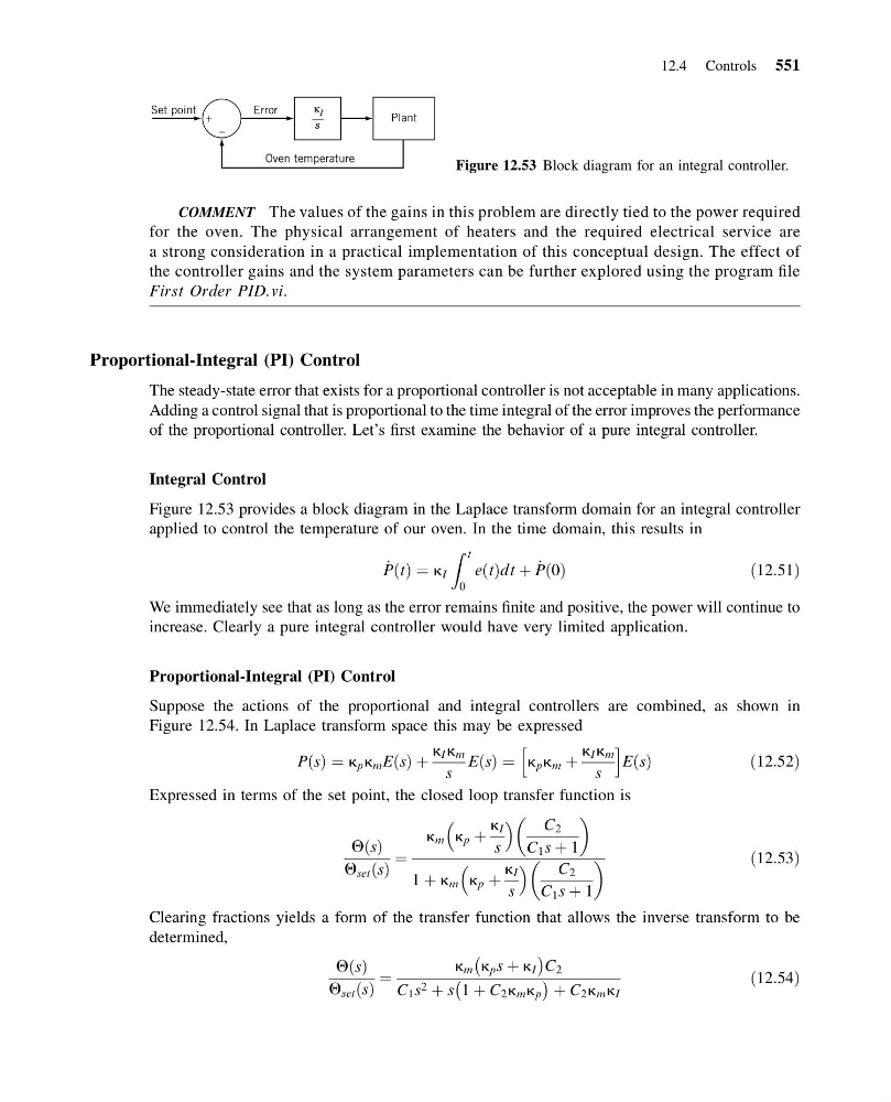
Figure 12.53 provides a block diagram in the Laplace transform domain for an integral controller
applied to control the temperature of our oven. In the time domain, this results in
_
P t
ð Þ ¼ k I
Z t
0
e t
ð Þdt þ _
P 0
ð Þ
ð12:51Þ
We immediately see that as long as the error remains finite and positive, the power will continue to
increase. Clearly a pure integral controller would have very limited application.
Proportional-Integral (PI) Control
Suppose the actions of the proportional and integral controllers are combined, as shown in
Figure 12.54. In Laplace transform space this may be expressed
P s
ð Þ ¼ k p k m E s
ð Þ þ
k I k m
s
E s
ð Þ ¼ k p k m þ
k I k m
s
h
i
E s
ð Þ
ð12:52Þ
Expressed in terms of the set point, the closed loop transfer function is
Q s
ð Þ
Q set s
ð Þ
¼
k m k p þ
k I
s
C 2
C 1 s þ 1
1 þ k m k p þ
k I
s
C 2
C 1 s þ 1
ð12:53Þ
Clearing fractions yields a form of the transfer function that allows the inverse transform to be
determined,
Q s
ð Þ
Q set s
ð Þ
¼
k m k p s þ k I
À
Á C 2
C 1 s 2 þ s 1 þ C 2 k m k p
À
Á þ C 2 k m k I
ð12:54Þ
+
–
Plant
Oven temperature
Error
Set point
κ I
s
Figure 12.53 Block diagram for an integral controller.
12.4 Controls 551
13:54:15 Page 551
COMMENT The values of the gains in this problem are directly tied to the power required
for the oven. The physical arrangement of heaters and the required electrical service are
a strong consideration in a practical implementation of this conceptual design. The effect of
the controller gains and the system parameters can be further explored using the program file
First Order PID.vi.
Proportional-Integral (PI) Control
The steady-state error that exists for a proportional controller is not acceptable in many applications.
Adding a control signal that is proportional to the time integral of the error improves the performance
of the proportional controller. Let’s first examine the behavior of a pure integral controller.
Integral Control
Figure 12.53 provides a block diagram in the Laplace transform domain for an integral controller
applied to control the temperature of our oven. In the time domain, this results in
_
P t
ð Þ ¼ k I
Z t
0
e t
ð Þdt þ _
P 0
ð Þ
ð12:51Þ
We immediately see that as long as the error remains finite and positive, the power will continue to
increase. Clearly a pure integral controller would have very limited application.
Proportional-Integral (PI) Control
Suppose the actions of the proportional and integral controllers are combined, as shown in
Figure 12.54. In Laplace transform space this may be expressed
P s
ð Þ ¼ k p k m E s
ð Þ þ
k I k m
s
E s
ð Þ ¼ k p k m þ
k I k m
s
h
i
E s
ð Þ
ð12:52Þ
Expressed in terms of the set point, the closed loop transfer function is
Q s
ð Þ
Q set s
ð Þ
¼
k m k p þ
k I
s
C 2
C 1 s þ 1
1 þ k m k p þ
k I
s
C 2
C 1 s þ 1
ð12:53Þ
Clearing fractions yields a form of the transfer function that allows the inverse transform to be
determined,
Q s
ð Þ
Q set s
ð Þ
¼
k m k p s þ k I
À
Á C 2
C 1 s 2 þ s 1 þ C 2 k m k p
À
Á þ C 2 k m k I
ð12:54Þ
+
–
Plant
Oven temperature
Error
Set point
κ I
s
Figure 12.53 Block diagram for an integral controller.
12.4 Controls 551