

E1C12 09/14/2010
13:54:14 Page 546
Block Diagrams
A very useful representation of feedback control systems is accomplished using block diagrams. We
first describe the basic elements of a block diagram.
Operational Blocks
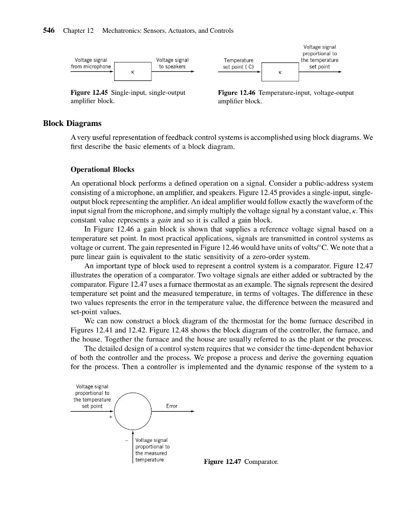
An operational block performs a defined operation on a signal. Consider a public-address system
consisting of a microphone, an amplifier, and speakers. Figure 12.45 provides a single-input, singleoutput block representing the amplifier. An ideal amplifier would follow exactly the waveform of the
input signal from the microphone, and simply multiply the voltage signal by a constant value, k. This
constant value represents a gain and so it is called a gain block.
In Figure 12.46 a gain block is shown that supplies a reference voltage signal based on a
temperature set point. In most practical applications, signals are transmitted in control systems as
voltage or current. The gain represented in Figure 12.46 would have units of volts/
C. We note that a
pure linear gain is equivalent to the static sensitivity of a zero-order system.
An important type of block used to represent a control system is a comparator. Figure 12.47
illustrates the operation of a comparator. Two voltage signals are either added or subtracted by the
comparator. Figure 12.47 uses a furnace thermostat as an example. The signals represent the desired
temperature set point and the measured temperature, in terms of voltages. The difference in these
two values represents the error in the temperature value, the difference between the measured and
set-point values.
We can now construct a block diagram of the thermostat for the home furnace described in
Figures 12.41 and 12.42. Figure 12.48 shows the block diagram of the controller, the furnace, and
the house. Together the furnace and the house are usually referred to as the plant or the process.
The detailed design of a control system requires that we consider the time-dependent behavior
of both the controller and the process. We propose a process and derive the governing equation
for the process. Then a controller is implemented and the dynamic response of the system to a
κ
Voltage signal
from microphone
Voltage signal
to speakers
Figure 12.45 Single-input, single-output
amplifier block.
κ
Temperature
set point ( C)
Voltage signal
proportional to
the temperature
set point
Figure 12.46 Temperature-input, voltage-output
amplifier block.
Error
Voltage signal
proportional to
the temperature
set point
Voltage signal
proportional to
the measured
temperature
–
+
Figure 12.47 Comparator.
546 Chapter 12 Mechatronics: Sensors, Actuators, and Controls
13:54:14 Page 546
Block Diagrams
A very useful representation of feedback control systems is accomplished using block diagrams. We
first describe the basic elements of a block diagram.
Operational Blocks
An operational block performs a defined operation on a signal. Consider a public-address system
consisting of a microphone, an amplifier, and speakers. Figure 12.45 provides a single-input, singleoutput block representing the amplifier. An ideal amplifier would follow exactly the waveform of the
input signal from the microphone, and simply multiply the voltage signal by a constant value, k. This
constant value represents a gain and so it is called a gain block.
In Figure 12.46 a gain block is shown that supplies a reference voltage signal based on a
temperature set point. In most practical applications, signals are transmitted in control systems as
voltage or current. The gain represented in Figure 12.46 would have units of volts/
C. We note that a
pure linear gain is equivalent to the static sensitivity of a zero-order system.
An important type of block used to represent a control system is a comparator. Figure 12.47
illustrates the operation of a comparator. Two voltage signals are either added or subtracted by the
comparator. Figure 12.47 uses a furnace thermostat as an example. The signals represent the desired
temperature set point and the measured temperature, in terms of voltages. The difference in these
two values represents the error in the temperature value, the difference between the measured and
set-point values.
We can now construct a block diagram of the thermostat for the home furnace described in
Figures 12.41 and 12.42. Figure 12.48 shows the block diagram of the controller, the furnace, and
the house. Together the furnace and the house are usually referred to as the plant or the process.
The detailed design of a control system requires that we consider the time-dependent behavior
of both the controller and the process. We propose a process and derive the governing equation
for the process. Then a controller is implemented and the dynamic response of the system to a
κ
Voltage signal
from microphone
Voltage signal
to speakers
Figure 12.45 Single-input, single-output
amplifier block.
κ
Temperature
set point ( C)
Voltage signal
proportional to
the temperature
set point
Figure 12.46 Temperature-input, voltage-output
amplifier block.
Error
Voltage signal
proportional to
the temperature
set point
Voltage signal
proportional to
the measured
temperature
–
+
Figure 12.47 Comparator.
546 Chapter 12 Mechatronics: Sensors, Actuators, and Controls