

E1C12 09/14/2010
13:54:14 Page 547
step-change in the set point is derived. A key point in this model is the use of a stationary operating
set point.
Model for Oven Control
Plant Model
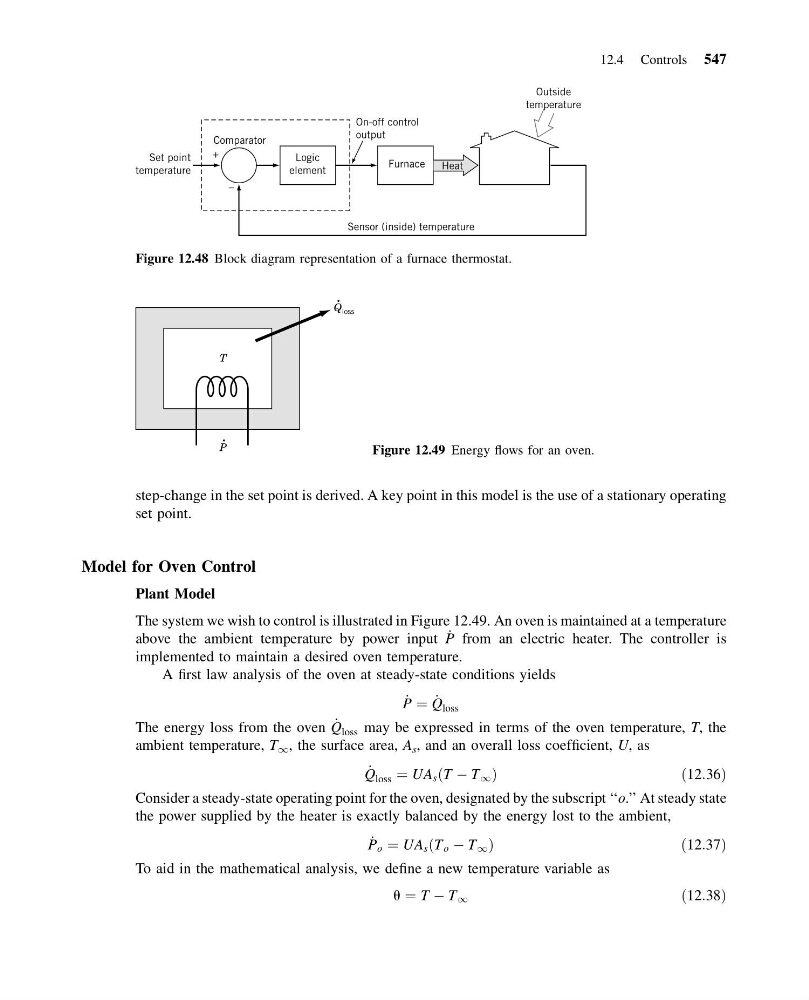
The system we wish to control is illustrated in Figure 12.49. An oven is maintained at a temperature
above the ambient temperature by power input _
P from an electric heater. The controller is
implemented to maintain a desired oven temperature.
A first law analysis of the oven at steady-state conditions yields
_
P ¼ _
Q loss
The energy loss from the oven _
Q loss may be expressed in terms of the oven temperature, T, the
ambient temperature, T 1 , the surface area, A s , and an overall loss coefficient, U, as
_
Q loss ¼ UA s T À T 1
ð
Þ
ð 12:36Þ
Consider a steady-state operating point for the oven, designated by the subscript ‘‘o.’’ At steady state
the power supplied by the heater is exactly balanced by the energy lost to the ambient,
_
P o ¼ UA s T o À T 1
ð
Þ
ð 12:37Þ
To aid in the mathematical analysis, we define a new temperature variable as
u ¼ T À T 1
ð12:38Þ
Sensor (inside) temperature
Comparator
On-off control
output
+
–
Logic
element
Set point
temperature
Furnace
Heat
Outside
temperature
Figure 12.48 Block diagram representation of a furnace thermostat.
Q loss
T
P
Figure 12.49 Energy flows for an oven.
12.4 Controls 547
13:54:14 Page 547
step-change in the set point is derived. A key point in this model is the use of a stationary operating
set point.
Model for Oven Control
Plant Model
The system we wish to control is illustrated in Figure 12.49. An oven is maintained at a temperature
above the ambient temperature by power input _
P from an electric heater. The controller is
implemented to maintain a desired oven temperature.
A first law analysis of the oven at steady-state conditions yields
_
P ¼ _
Q loss
The energy loss from the oven _
Q loss may be expressed in terms of the oven temperature, T, the
ambient temperature, T 1 , the surface area, A s , and an overall loss coefficient, U, as
_
Q loss ¼ UA s T À T 1
ð
Þ
ð 12:36Þ
Consider a steady-state operating point for the oven, designated by the subscript ‘‘o.’’ At steady state
the power supplied by the heater is exactly balanced by the energy lost to the ambient,
_
P o ¼ UA s T o À T 1
ð
Þ
ð 12:37Þ
To aid in the mathematical analysis, we define a new temperature variable as
u ¼ T À T 1
ð12:38Þ
Sensor (inside) temperature
Comparator
On-off control
output
+
–
Logic
element
Set point
temperature
Furnace
Heat
Outside
temperature
Figure 12.48 Block diagram representation of a furnace thermostat.
Q loss
T
P
Figure 12.49 Energy flows for an oven.
12.4 Controls 547