

E1C12 09/14/2010
13:54:13 Page 541
system there are no sensors to monitor the amount of water applied to the lawn; in fact, all that the control
system is accomplishing is to open and, later, to close the faucet.
More advanced automatic control systems implement a closed-loop control. For the present
example, it might be desired to apply 100 gallons (379 liters) of water to the lawn. A flow meter that
sensed the total water flow that had occurred could be used to provide feedback to the control system to
allow the faucet to be closed when the flow totaled 100 gallons. Such flow meters are common and serve
as water meters. The term closed-loop or feedback control simply means that the variable that is to be
controlled is being measured, and that the control system in some way uses this measurement to exert the
control.
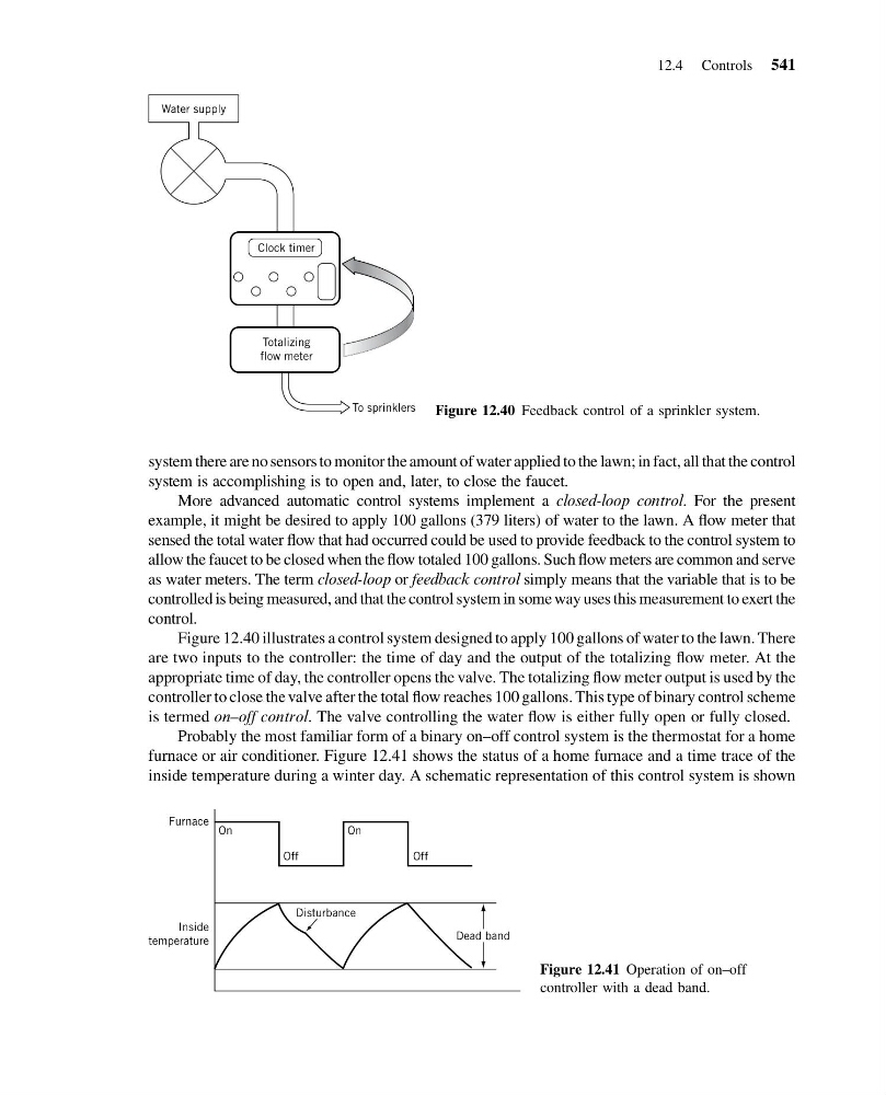
Figure 12.40 illustrates a control system designed to apply 100 gallons of water to the lawn. There
are two inputs to the controller: the time of day and the output of the totalizing flow meter. At the
appropriate time of day, the controller opens the valve. The totalizing flow meter output is used by the
controller to close the valve after the total flow reaches 100 gallons. This type of binary control scheme
is termed on–off control. The valve controlling the water flow is either fully open or fully closed.
Probably the most familiar form of a binary on–off control system is the thermostat for a home
furnace or air conditioner. Figure 12.41 shows the status of a home furnace and a time trace of the
inside temperature during a winter day. A schematic representation of this control system is shown
Water supply
To sprinklers
Clock timer
Totalizing
flow meter
Figure 12.40 Feedback control of a sprinkler system.
Inside
temperature
Furnace
On
Off
Off
Disturbance
Dead band
On
Figure 12.41 Operation of on–off
controller with a dead band.
12.4 Controls 541
13:54:13 Page 541
system there are no sensors to monitor the amount of water applied to the lawn; in fact, all that the control
system is accomplishing is to open and, later, to close the faucet.
More advanced automatic control systems implement a closed-loop control. For the present
example, it might be desired to apply 100 gallons (379 liters) of water to the lawn. A flow meter that
sensed the total water flow that had occurred could be used to provide feedback to the control system to
allow the faucet to be closed when the flow totaled 100 gallons. Such flow meters are common and serve
as water meters. The term closed-loop or feedback control simply means that the variable that is to be
controlled is being measured, and that the control system in some way uses this measurement to exert the
control.
Figure 12.40 illustrates a control system designed to apply 100 gallons of water to the lawn. There
are two inputs to the controller: the time of day and the output of the totalizing flow meter. At the
appropriate time of day, the controller opens the valve. The totalizing flow meter output is used by the
controller to close the valve after the total flow reaches 100 gallons. This type of binary control scheme
is termed on–off control. The valve controlling the water flow is either fully open or fully closed.
Probably the most familiar form of a binary on–off control system is the thermostat for a home
furnace or air conditioner. Figure 12.41 shows the status of a home furnace and a time trace of the
inside temperature during a winter day. A schematic representation of this control system is shown
Water supply
To sprinklers
Clock timer
Totalizing
flow meter
Figure 12.40 Feedback control of a sprinkler system.
Inside
temperature
Furnace
On
Off
Off
Disturbance
Dead band
On
Figure 12.41 Operation of on–off
controller with a dead band.
12.4 Controls 541