

E1C12 09/14/2010
13:54:13 Page 540
time between each signal cycle coupled with the internal flow loss character of the valve determines
the average flow. Valve response time can be defined in several ways but all are consistent with the
methods used in Chapter 3. The 90% response time, t 90 , is the time required to either fill or exhaust a
target device chamber through a valve port, in effect a step function response. There is a separate
response time for filling or exhausting. Either way,
t 90 ¼ m þ F8
ð 12:24Þ
where m is the valve lag time between when the signal is applied and steady flow is established at the
designated port, F is the reciprocal of the average flow rate through the port, and 8 is the volume of
the target device chamber. For example, a valve having an F of 0.54 ms/cc and a lag time of 20 ms
requires t 90 ¼ 155 ms to fill a 250-cc chamber. Alternatively, the valve frequency response can be
found by cycling the valve with a sine wave electrical signal and measuring the flow rate through the
valve. The valve frequency bandwidth is thus established by its À3 dB point.
12.4 CONTROLS
Control of a process or system can be exerted in a wide variety of ways. Suppose our goal is to create
a healthy lawn by appropriate watering. Each day we could monitor the weather forecast, take into
account the probability of precipitation, and choose whether to water and for how long. We could
choose to water all of the lawn or just those parts most subject to stress from heat and lack of
moisture. If we choose to water, we could place the sprinklers and turn on the faucet (remembering
to shut off the flow at an appropriate later time)!
All of the functions described above for lawn care are completely reasonable for a person to
accomplish, and they represent the functioning of an intelligent controller. Suppose we wish to
introduce some automation into the process.
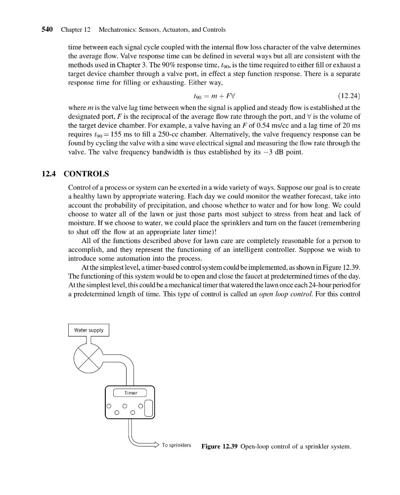
At the simplest level, a timer-based control system could be implemented, as shown in Figure 12.39.
The functioning of this system would be to open and close the faucet at predetermined times of the day.
At the simplest level, this could be a mechanical timer that watered the lawn once each 24-hour period for
a predetermined length of time. This type of control is called an open loop control. For this control
Water supply
Timer
To sprinklers
Figure 12.39 Open-loop control of a sprinkler system.
540 Chapter 12 Mechatronics: Sensors, Actuators, and Controls
13:54:13 Page 540
time between each signal cycle coupled with the internal flow loss character of the valve determines
the average flow. Valve response time can be defined in several ways but all are consistent with the
methods used in Chapter 3. The 90% response time, t 90 , is the time required to either fill or exhaust a
target device chamber through a valve port, in effect a step function response. There is a separate
response time for filling or exhausting. Either way,
t 90 ¼ m þ F8
ð 12:24Þ
where m is the valve lag time between when the signal is applied and steady flow is established at the
designated port, F is the reciprocal of the average flow rate through the port, and 8 is the volume of
the target device chamber. For example, a valve having an F of 0.54 ms/cc and a lag time of 20 ms
requires t 90 ¼ 155 ms to fill a 250-cc chamber. Alternatively, the valve frequency response can be
found by cycling the valve with a sine wave electrical signal and measuring the flow rate through the
valve. The valve frequency bandwidth is thus established by its À3 dB point.
12.4 CONTROLS
Control of a process or system can be exerted in a wide variety of ways. Suppose our goal is to create
a healthy lawn by appropriate watering. Each day we could monitor the weather forecast, take into
account the probability of precipitation, and choose whether to water and for how long. We could
choose to water all of the lawn or just those parts most subject to stress from heat and lack of
moisture. If we choose to water, we could place the sprinklers and turn on the faucet (remembering
to shut off the flow at an appropriate later time)!
All of the functions described above for lawn care are completely reasonable for a person to
accomplish, and they represent the functioning of an intelligent controller. Suppose we wish to
introduce some automation into the process.
At the simplest level, a timer-based control system could be implemented, as shown in Figure 12.39.
The functioning of this system would be to open and close the faucet at predetermined times of the day.
At the simplest level, this could be a mechanical timer that watered the lawn once each 24-hour period for
a predetermined length of time. This type of control is called an open loop control. For this control
Water supply
Timer
To sprinklers
Figure 12.39 Open-loop control of a sprinkler system.
540 Chapter 12 Mechatronics: Sensors, Actuators, and Controls