

E1C12 09/14/2010
13:54:13 Page 538
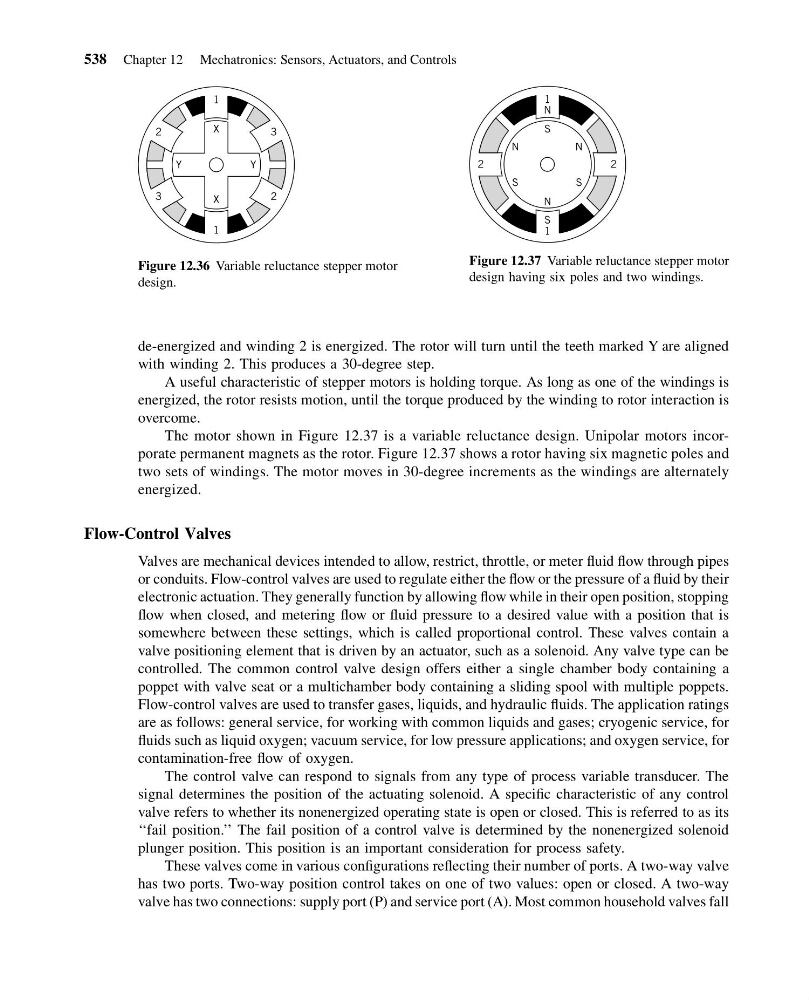
de-energized and winding 2 is energized. The rotor will turn until the teeth marked Y are aligned
with winding 2. This produces a 30-degree step.
A useful characteristic of stepper motors is holding torque. As long as one of the windings is
energized, the rotor resists motion, until the torque produced by the winding to rotor interaction is
overcome.
The motor shown in Figure 12.37 is a variable reluctance design. Unipolar motors incorporate permanent magnets as the rotor. Figure 12.37 shows a rotor having six magnetic poles and
two sets of windings. The motor moves in 30-degree increments as the windings are alternately
energized.
Flow-Control Valves
Valves are mechanical devices intended to allow, restrict, throttle, or meter fluid flow through pipes
or conduits. Flow-control valves are used to regulate either the flow or the pressure of a fluid by their
electronic actuation. They generally function by allowing flow while in their open position, stopping
flow when closed, and metering flow or fluid pressure to a desired value with a position that is
somewhere between these settings, which is called proportional control. These valves contain a
valve positioning element that is driven by an actuator, such as a solenoid. Any valve type can be
controlled. The common control valve design offers either a single chamber body containing a
poppet with valve seat or a multichamber body containing a sliding spool with multiple poppets.
Flow-control valves are used to transfer gases, liquids, and hydraulic fluids. The application ratings
are as follows: general service, for working with common liquids and gases; cryogenic service, for
fluids such as liquid oxygen; vacuum service, for low pressure applications; and oxygen service, for
contamination-free flow of oxygen.
The control valve can respond to signals from any type of process variable transducer. The
signal determines the position of the actuating solenoid. A specific characteristic of any control
valve refers to whether its nonenergized operating state is open or closed. This is referred to as its
‘‘fail position.’’ The fail position of a control valve is determined by the nonenergized solenoid
plunger position. This position is an important consideration for process safety.
These valves come in various configurations reflecting their number of ports. A two-way valve
has two ports. Two-way position control takes on one of two values: open or closed. A two-way
valve has two connections: supply port (P) and service port (A). Most common household valves fall
1
1
X
X
Y
Y
3
2
2
3
Figure 12.36 Variable reluctance stepper motor
design.
2
2
1
S
S
S
S
N
N
N
N
1
Figure 12.37 Variable reluctance stepper motor
design having six poles and two windings.
538 Chapter 12 Mechatronics: Sensors, Actuators, and Controls
13:54:13 Page 538
de-energized and winding 2 is energized. The rotor will turn until the teeth marked Y are aligned
with winding 2. This produces a 30-degree step.
A useful characteristic of stepper motors is holding torque. As long as one of the windings is
energized, the rotor resists motion, until the torque produced by the winding to rotor interaction is
overcome.
The motor shown in Figure 12.37 is a variable reluctance design. Unipolar motors incorporate permanent magnets as the rotor. Figure 12.37 shows a rotor having six magnetic poles and
two sets of windings. The motor moves in 30-degree increments as the windings are alternately
energized.
Flow-Control Valves
Valves are mechanical devices intended to allow, restrict, throttle, or meter fluid flow through pipes
or conduits. Flow-control valves are used to regulate either the flow or the pressure of a fluid by their
electronic actuation. They generally function by allowing flow while in their open position, stopping
flow when closed, and metering flow or fluid pressure to a desired value with a position that is
somewhere between these settings, which is called proportional control. These valves contain a
valve positioning element that is driven by an actuator, such as a solenoid. Any valve type can be
controlled. The common control valve design offers either a single chamber body containing a
poppet with valve seat or a multichamber body containing a sliding spool with multiple poppets.
Flow-control valves are used to transfer gases, liquids, and hydraulic fluids. The application ratings
are as follows: general service, for working with common liquids and gases; cryogenic service, for
fluids such as liquid oxygen; vacuum service, for low pressure applications; and oxygen service, for
contamination-free flow of oxygen.
The control valve can respond to signals from any type of process variable transducer. The
signal determines the position of the actuating solenoid. A specific characteristic of any control
valve refers to whether its nonenergized operating state is open or closed. This is referred to as its
‘‘fail position.’’ The fail position of a control valve is determined by the nonenergized solenoid
plunger position. This position is an important consideration for process safety.
These valves come in various configurations reflecting their number of ports. A two-way valve
has two ports. Two-way position control takes on one of two values: open or closed. A two-way
valve has two connections: supply port (P) and service port (A). Most common household valves fall
1
1
X
X
Y
Y
3
2
2
3
Figure 12.36 Variable reluctance stepper motor
design.
2
2
1
S
S
S
S
N
N
N
N
1
Figure 12.37 Variable reluctance stepper motor
design having six poles and two windings.
538 Chapter 12 Mechatronics: Sensors, Actuators, and Controls