

E1C12 09/14/2010
13:54:13 Page 537
where
F ¼ force on plunger
N ¼ number of turns of wire in the electromagnetic
I ¼ current
m ¼ magnetic permeability of air (4p  10
À7
H=m)
d ¼ size of the air gap
A ¼ plunger cross-sectional area
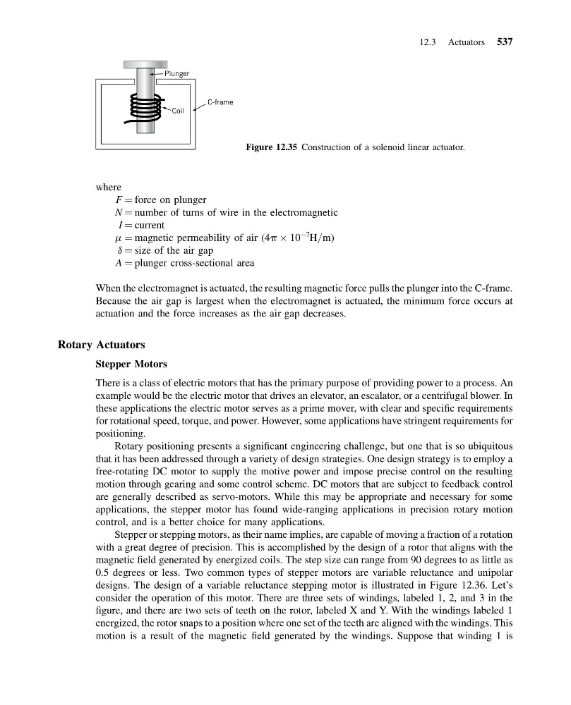
When the electromagnet is actuated, the resulting magnetic force pulls the plunger into the C-frame.
Because the air gap is largest when the electromagnet is actuated, the minimum force occurs at
actuation and the force increases as the air gap decreases.
Rotary Actuators
Stepper Motors
There is a class of electric motors that has the primary purpose of providing power to a process. An
example would be the electric motor that drives an elevator, an escalator, or a centrifugal blower. In
these applications the electric motor serves as a prime mover, with clear and specific requirements
for rotational speed, torque, and power. However, some applications have stringent requirements for
positioning.
Rotary positioning presents a significant engineering challenge, but one that is so ubiquitous
that it has been addressed through a variety of design strategies. One design strategy is to employ a
free-rotating DC motor to supply the motive power and impose precise control on the resulting
motion through gearing and some control scheme. DC motors that are subject to feedback control
are generally described as servo-motors. While this may be appropriate and necessary for some
applications, the stepper motor has found wide-ranging applications in precision rotary motion
control, and is a better choice for many applications.
Stepper or stepping motors, as their name implies, are capable of moving a fraction of a rotation
with a great degree of precision. This is accomplished by the design of a rotor that aligns with the
magnetic field generated by energized coils. The step size can range from 90 degrees to as little as
0.5 degrees or less. Two common types of stepper motors are variable reluctance and unipolar
designs. The design of a variable reluctance stepping motor is illustrated in Figure 12.36. Let’s
consider the operation of this motor. There are three sets of windings, labeled 1, 2, and 3 in the
figure, and there are two sets of teeth on the rotor, labeled X and Y. With the windings labeled 1
energized, the rotor snaps to a position where one set of the teeth are aligned with the windings. This
motion is a result of the magnetic field generated by the windings. Suppose that winding 1 is
Coil
C-frame
Plunger
Figure 12.35 Construction of a solenoid linear actuator.
12.3 Actuators 537
13:54:13 Page 537
where
F ¼ force on plunger
N ¼ number of turns of wire in the electromagnetic
I ¼ current
m ¼ magnetic permeability of air (4p  10
À7
H=m)
d ¼ size of the air gap
A ¼ plunger cross-sectional area
When the electromagnet is actuated, the resulting magnetic force pulls the plunger into the C-frame.
Because the air gap is largest when the electromagnet is actuated, the minimum force occurs at
actuation and the force increases as the air gap decreases.
Rotary Actuators
Stepper Motors
There is a class of electric motors that has the primary purpose of providing power to a process. An
example would be the electric motor that drives an elevator, an escalator, or a centrifugal blower. In
these applications the electric motor serves as a prime mover, with clear and specific requirements
for rotational speed, torque, and power. However, some applications have stringent requirements for
positioning.
Rotary positioning presents a significant engineering challenge, but one that is so ubiquitous
that it has been addressed through a variety of design strategies. One design strategy is to employ a
free-rotating DC motor to supply the motive power and impose precise control on the resulting
motion through gearing and some control scheme. DC motors that are subject to feedback control
are generally described as servo-motors. While this may be appropriate and necessary for some
applications, the stepper motor has found wide-ranging applications in precision rotary motion
control, and is a better choice for many applications.
Stepper or stepping motors, as their name implies, are capable of moving a fraction of a rotation
with a great degree of precision. This is accomplished by the design of a rotor that aligns with the
magnetic field generated by energized coils. The step size can range from 90 degrees to as little as
0.5 degrees or less. Two common types of stepper motors are variable reluctance and unipolar
designs. The design of a variable reluctance stepping motor is illustrated in Figure 12.36. Let’s
consider the operation of this motor. There are three sets of windings, labeled 1, 2, and 3 in the
figure, and there are two sets of teeth on the rotor, labeled X and Y. With the windings labeled 1
energized, the rotor snaps to a position where one set of the teeth are aligned with the windings. This
motion is a result of the magnetic field generated by the windings. Suppose that winding 1 is
Coil
C-frame
Plunger
Figure 12.35 Construction of a solenoid linear actuator.
12.3 Actuators 537