

E1C12 09/14/2010
13:54:9 Page 515
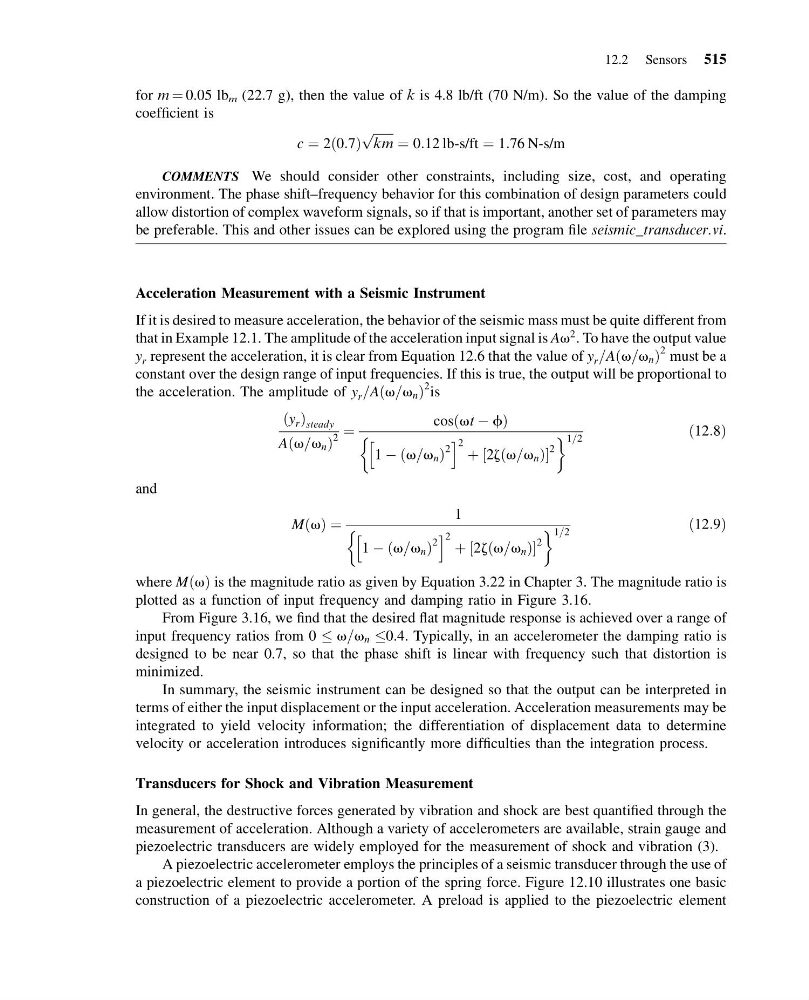
for m ¼ 0.05 lb m (22.7 g), then the value of k is 4.8 lb/ft (70 N/m). So the value of the damping
coefficient is
c ¼ 2 0:7
ð Þ
ffiffiffiffiffiffi ffi
km
p
¼ 0:12 lb-s/ft ¼ 1:76 N-s/m
COMMENTS We should consider other constraints, including size, cost, and operating
environment. The phase shift–frequency behavior for this combination of design parameters could
allow distortion of complex waveform signals, so if that is important, another set of parameters may
be preferable. This and other issues can be explored using the program file seismic_transducer.vi.
Acceleration Measurement with a Seismic Instrument
If it is desired to measure acceleration, the behavior of the seismic mass must be quite different from
that in Example 12.1. The amplitude of the acceleration input signal is Av
2 . To have the output value
y r represent the acceleration, it is clear from Equation 12.6 that the value of y r =A v=v n
ð
Þ
2 must be a
constant over the design range of input frequencies. If this is true, the output will be proportional to
the acceleration. The amplitude of y r =A v=v n
ð
Þ
2 is
y r
ð Þ steady
A v=v n
ð
Þ
2
¼
cos vt À f
ð
Þ
1 À v=v n
ð
Þ
2
h
i 2 þ 2z v=v n
ð
Þ
½
2
&
' 1=2
ð12:8Þ
and
M v
ð Þ ¼
1
1 À v=v n
ð
Þ
2
h
i 2 þ 2z v=v n
ð
Þ
½
2
&
' 1=2
ð12:9Þ
where M v
ð Þ is the magnitude ratio as given by Equation 3.22 in Chapter 3. The magnitude ratio is
plotted as a function of input frequency and damping ratio in Figure 3.16.
From Figure 3.16, we find that the desired flat magnitude response is achieved over a range of
input frequency ratios from 0 v=v n 0.4. Typically, in an accelerometer the damping ratio is
designed to be near 0.7, so that the phase shift is linear with frequency such that distortion is
minimized.
In summary, the seismic instrument can be designed so that the output can be interpreted in
terms of either the input displacement or the input acceleration. Acceleration measurements may be
integrated to yield velocity information; the differentiation of displacement data to determine
velocity or acceleration introduces significantly more difficulties than the integration process.
Transducers for Shock and Vibration Measurement
In general, the destructive forces generated by vibration and shock are best quantified through the
measurement of acceleration. Although a variety of accelerometers are available, strain gauge and
piezoelectric transducers are widely employed for the measurement of shock and vibration (3).
A piezoelectric accelerometer employs the principles of a seismic transducer through the use of
a piezoelectric element to provide a portion of the spring force. Figure 12.10 illustrates one basic
construction of a piezoelectric accelerometer. A preload is applied to the piezoelectric element
12.2 Sensors 515
13:54:9 Page 515
for m ¼ 0.05 lb m (22.7 g), then the value of k is 4.8 lb/ft (70 N/m). So the value of the damping
coefficient is
c ¼ 2 0:7
ð Þ
ffiffiffiffiffiffi ffi
km
p
¼ 0:12 lb-s/ft ¼ 1:76 N-s/m
COMMENTS We should consider other constraints, including size, cost, and operating
environment. The phase shift–frequency behavior for this combination of design parameters could
allow distortion of complex waveform signals, so if that is important, another set of parameters may
be preferable. This and other issues can be explored using the program file seismic_transducer.vi.
Acceleration Measurement with a Seismic Instrument
If it is desired to measure acceleration, the behavior of the seismic mass must be quite different from
that in Example 12.1. The amplitude of the acceleration input signal is Av
2 . To have the output value
y r represent the acceleration, it is clear from Equation 12.6 that the value of y r =A v=v n
ð
Þ
2 must be a
constant over the design range of input frequencies. If this is true, the output will be proportional to
the acceleration. The amplitude of y r =A v=v n
ð
Þ
2 is
y r
ð Þ steady
A v=v n
ð
Þ
2
¼
cos vt À f
ð
Þ
1 À v=v n
ð
Þ
2
h
i 2 þ 2z v=v n
ð
Þ
½
2
&
' 1=2
ð12:8Þ
and
M v
ð Þ ¼
1
1 À v=v n
ð
Þ
2
h
i 2 þ 2z v=v n
ð
Þ
½
2
&
' 1=2
ð12:9Þ
where M v
ð Þ is the magnitude ratio as given by Equation 3.22 in Chapter 3. The magnitude ratio is
plotted as a function of input frequency and damping ratio in Figure 3.16.
From Figure 3.16, we find that the desired flat magnitude response is achieved over a range of
input frequency ratios from 0 v=v n 0.4. Typically, in an accelerometer the damping ratio is
designed to be near 0.7, so that the phase shift is linear with frequency such that distortion is
minimized.
In summary, the seismic instrument can be designed so that the output can be interpreted in
terms of either the input displacement or the input acceleration. Acceleration measurements may be
integrated to yield velocity information; the differentiation of displacement data to determine
velocity or acceleration introduces significantly more difficulties than the integration process.
Transducers for Shock and Vibration Measurement
In general, the destructive forces generated by vibration and shock are best quantified through the
measurement of acceleration. Although a variety of accelerometers are available, strain gauge and
piezoelectric transducers are widely employed for the measurement of shock and vibration (3).
A piezoelectric accelerometer employs the principles of a seismic transducer through the use of
a piezoelectric element to provide a portion of the spring force. Figure 12.10 illustrates one basic
construction of a piezoelectric accelerometer. A preload is applied to the piezoelectric element
12.2 Sensors 515