

E1C12 09/14/2010
13:54:9 Page 507
in the current in one coil induces an electromotive force (emf) in the second coil according to
Faraday’s law. The application of this inductance principle to the measurement of distance begins by
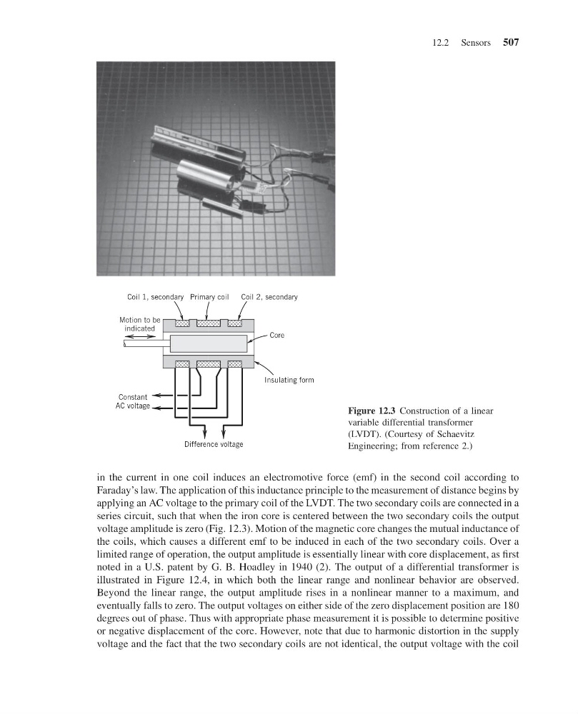
applying an AC voltage to the primary coil of the LVDT. The two secondary coils are connected in a
series circuit, such that when the iron core is centered between the two secondary coils the output
voltage amplitude is zero (Fig. 12.3). Motion of the magnetic core changes the mutual inductance of
the coils, which causes a different emf to be induced in each of the two secondary coils. Over a
limited range of operation, the output amplitude is essentially linear with core displacement, as first
noted in a U.S. patent by G. B. Hoadley in 1940 (2). The output of a differential transformer is
illustrated in Figure 12.4, in which both the linear range and nonlinear behavior are observed.
Beyond the linear range, the output amplitude rises in a nonlinear manner to a maximum, and
eventually falls to zero. The output voltages on either side of the zero displacement position are 180
degrees out of phase. Thus with appropriate phase measurement it is possible to determine positive
or negative displacement of the core. However, note that due to harmonic distortion in the supply
voltage and the fact that the two secondary coils are not identical, the output voltage with the coil
Constant
AC voltage
Coil 1, secondary Primary coil
Core
Insulating form
Motion to be
indicated
Difference voltage
Coil 2, secondary
Figure 12.3 Construction of a linear
variable differential transformer
(LVDT). (Courtesy of Schaevitz
Engineering; from reference 2.)
12.2 Sensors 507
13:54:9 Page 507
in the current in one coil induces an electromotive force (emf) in the second coil according to
Faraday’s law. The application of this inductance principle to the measurement of distance begins by
applying an AC voltage to the primary coil of the LVDT. The two secondary coils are connected in a
series circuit, such that when the iron core is centered between the two secondary coils the output
voltage amplitude is zero (Fig. 12.3). Motion of the magnetic core changes the mutual inductance of
the coils, which causes a different emf to be induced in each of the two secondary coils. Over a
limited range of operation, the output amplitude is essentially linear with core displacement, as first
noted in a U.S. patent by G. B. Hoadley in 1940 (2). The output of a differential transformer is
illustrated in Figure 12.4, in which both the linear range and nonlinear behavior are observed.
Beyond the linear range, the output amplitude rises in a nonlinear manner to a maximum, and
eventually falls to zero. The output voltages on either side of the zero displacement position are 180
degrees out of phase. Thus with appropriate phase measurement it is possible to determine positive
or negative displacement of the core. However, note that due to harmonic distortion in the supply
voltage and the fact that the two secondary coils are not identical, the output voltage with the coil
Constant
AC voltage
Coil 1, secondary Primary coil
Core
Insulating form
Motion to be
indicated
Difference voltage
Coil 2, secondary
Figure 12.3 Construction of a linear
variable differential transformer
(LVDT). (Courtesy of Schaevitz
Engineering; from reference 2.)
12.2 Sensors 507