

E1C12 09/14/2010
13:54:8 Page 506
Wire-wound potentiometers display a stepwise output as the wiper contacts successive turns of
the wire winding. Conductive plastic potentiometers were developed to eliminate this stepwise
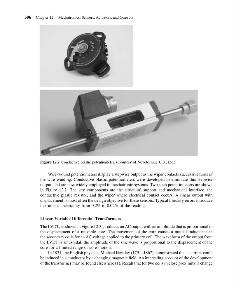
output, and are now widely employed in mechatronic systems. Two such potentiometers are shown
in Figure 12.2. The key components are the structural support and mechanical interface, the
conductive plastic resistor, and the wiper where electrical contact occurs. A linear output with
displacement is most often the design objective for these sensors. Typical linearity errors introduce
instrument uncertainty from 0.2% to 0.02% of the reading.
Linear Variable Differential Transformers
The LVDT, as shown in Figure 12.3, produces an AC output with an amplitude that is proportional to
the displacement of a movable core. The movement of the core causes a mutual inductance in
the secondary coils for an AC voltage applied to the primary coil. The waveform of the output from
the LVDT is sinusoidal; the amplitude of the sine wave is proportional to the displacement of the
core for a limited range of core motion.
In 1831, the English physicist Michael Faraday (1791–1867) demonstrated that a current could
be induced in a conductor by a changing magnetic field. An interesting account of the development
of the transformer may be found elsewhere (1). Recall that for two coils in close proximity, a change
Figure 12.2 Conductive plastic potentiometer. (Courtesy of Novotechnic U.S., Inc.).
506 Chapter 12 Mechatronics: Sensors, Actuators, and Controls
13:54:8 Page 506
Wire-wound potentiometers display a stepwise output as the wiper contacts successive turns of
the wire winding. Conductive plastic potentiometers were developed to eliminate this stepwise
output, and are now widely employed in mechatronic systems. Two such potentiometers are shown
in Figure 12.2. The key components are the structural support and mechanical interface, the
conductive plastic resistor, and the wiper where electrical contact occurs. A linear output with
displacement is most often the design objective for these sensors. Typical linearity errors introduce
instrument uncertainty from 0.2% to 0.02% of the reading.
Linear Variable Differential Transformers
The LVDT, as shown in Figure 12.3, produces an AC output with an amplitude that is proportional to
the displacement of a movable core. The movement of the core causes a mutual inductance in
the secondary coils for an AC voltage applied to the primary coil. The waveform of the output from
the LVDT is sinusoidal; the amplitude of the sine wave is proportional to the displacement of the
core for a limited range of core motion.
In 1831, the English physicist Michael Faraday (1791–1867) demonstrated that a current could
be induced in a conductor by a changing magnetic field. An interesting account of the development
of the transformer may be found elsewhere (1). Recall that for two coils in close proximity, a change
Figure 12.2 Conductive plastic potentiometer. (Courtesy of Novotechnic U.S., Inc.).
506 Chapter 12 Mechatronics: Sensors, Actuators, and Controls