

E1C12 09/14/2010
13:54:9 Page 508
centered is not zero but instead reaches a minimum. Resolution of an LVDT strongly depends on the
resolution of the measurement system used to determine its output. Resolutions down to the
nanometer range are available.
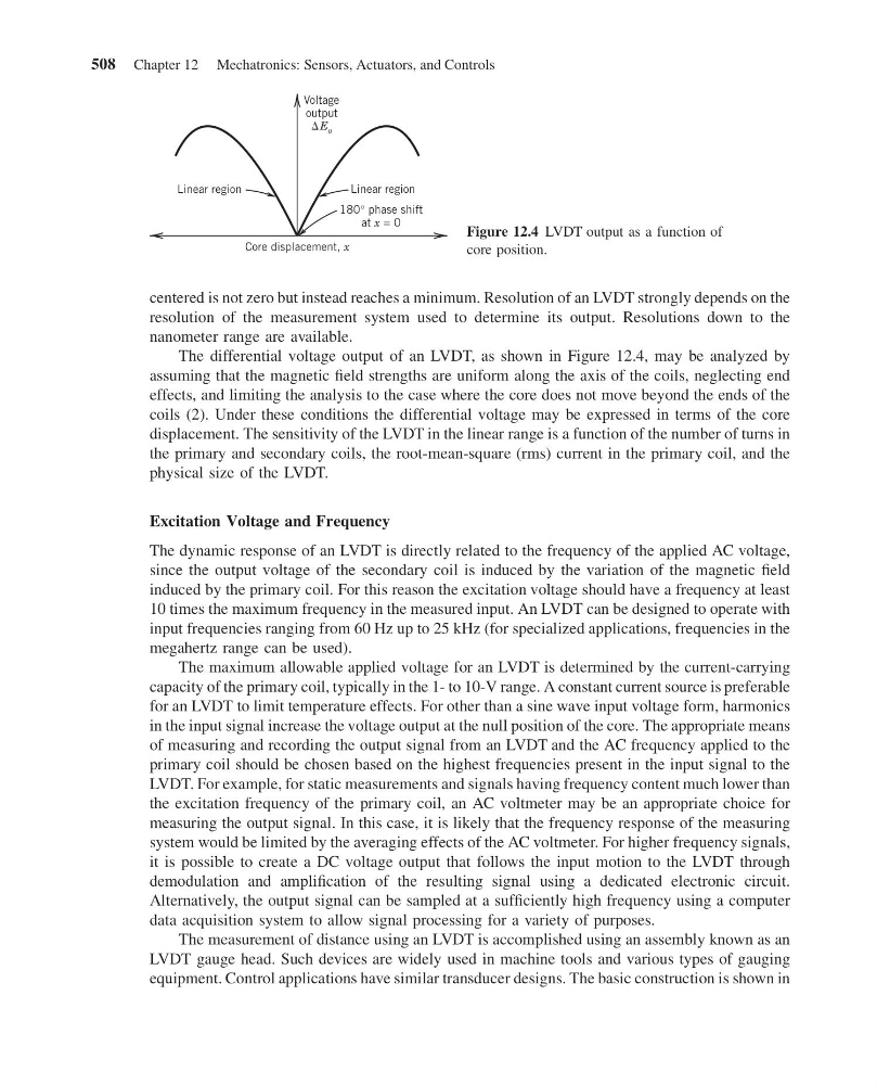
The differential voltage output of an LVDT, as shown in Figure 12.4, may be analyzed by
assuming that the magnetic field strengths are uniform along the axis of the coils, neglecting end
effects, and limiting the analysis to the case where the core does not move beyond the ends of the
coils (2). Under these conditions the differential voltage may be expressed in terms of the core
displacement. The sensitivity of the LVDT in the linear range is a function of the number of turns in
the primary and secondary coils, the root-mean-square (rms) current in the primary coil, and the
physical size of the LVDT.
Excitation Voltage and Frequency
The dynamic response of an LVDT is directly related to the frequency of the applied AC voltage,
since the output voltage of the secondary coil is induced by the variation of the magnetic field
induced by the primary coil. For this reason the excitation voltage should have a frequency at least
10 times the maximum frequency in the measured input. An LVDT can be designed to operate with
input frequencies ranging from 60 Hz up to 25 kHz (for specialized applications, frequencies in the
megahertz range can be used).
The maximum allowable applied voltage for an LVDT is determined by the current-carrying
capacity of the primary coil, typically in the 1- to 10-V range. A constant current source is preferable
for an LVDT to limit temperature effects. For other than a sine wave input voltage form, harmonics
in the input signal increase the voltage output at the null position of the core. The appropriate means
of measuring and recording the output signal from an LVDT and the AC frequency applied to the
primary coil should be chosen based on the highest frequencies present in the input signal to the
LVDT. For example, for static measurements and signals having frequency content much lower than
the excitation frequency of the primary coil, an AC voltmeter may be an appropriate choice for
measuring the output signal. In this case, it is likely that the frequency response of the measuring
system would be limited by the averaging effects of the AC voltmeter. For higher frequency signals,
it is possible to create a DC voltage output that follows the input motion to the LVDT through
demodulation and amplification of the resulting signal using a dedicated electronic circuit.
Alternatively, the output signal can be sampled at a sufficiently high frequency using a computer
data acquisition system to allow signal processing for a variety of purposes.
The measurement of distance using an LVDT is accomplished using an assembly known as an
LVDT gauge head. Such devices are widely used in machine tools and various types of gauging
equipment. Control applications have similar transducer designs. The basic construction is shown in
Core displacement, x
Voltage
output
E o
180° phase shift
Linear region
Linear region
at x = 0
Figure 12.4 LVDT output as a function of
core position.
508 Chapter 12 Mechatronics: Sensors, Actuators, and Controls
13:54:9 Page 508
centered is not zero but instead reaches a minimum. Resolution of an LVDT strongly depends on the
resolution of the measurement system used to determine its output. Resolutions down to the
nanometer range are available.
The differential voltage output of an LVDT, as shown in Figure 12.4, may be analyzed by
assuming that the magnetic field strengths are uniform along the axis of the coils, neglecting end
effects, and limiting the analysis to the case where the core does not move beyond the ends of the
coils (2). Under these conditions the differential voltage may be expressed in terms of the core
displacement. The sensitivity of the LVDT in the linear range is a function of the number of turns in
the primary and secondary coils, the root-mean-square (rms) current in the primary coil, and the
physical size of the LVDT.
Excitation Voltage and Frequency
The dynamic response of an LVDT is directly related to the frequency of the applied AC voltage,
since the output voltage of the secondary coil is induced by the variation of the magnetic field
induced by the primary coil. For this reason the excitation voltage should have a frequency at least
10 times the maximum frequency in the measured input. An LVDT can be designed to operate with
input frequencies ranging from 60 Hz up to 25 kHz (for specialized applications, frequencies in the
megahertz range can be used).
The maximum allowable applied voltage for an LVDT is determined by the current-carrying
capacity of the primary coil, typically in the 1- to 10-V range. A constant current source is preferable
for an LVDT to limit temperature effects. For other than a sine wave input voltage form, harmonics
in the input signal increase the voltage output at the null position of the core. The appropriate means
of measuring and recording the output signal from an LVDT and the AC frequency applied to the
primary coil should be chosen based on the highest frequencies present in the input signal to the
LVDT. For example, for static measurements and signals having frequency content much lower than
the excitation frequency of the primary coil, an AC voltmeter may be an appropriate choice for
measuring the output signal. In this case, it is likely that the frequency response of the measuring
system would be limited by the averaging effects of the AC voltmeter. For higher frequency signals,
it is possible to create a DC voltage output that follows the input motion to the LVDT through
demodulation and amplification of the resulting signal using a dedicated electronic circuit.
Alternatively, the output signal can be sampled at a sufficiently high frequency using a computer
data acquisition system to allow signal processing for a variety of purposes.
The measurement of distance using an LVDT is accomplished using an assembly known as an
LVDT gauge head. Such devices are widely used in machine tools and various types of gauging
equipment. Control applications have similar transducer designs. The basic construction is shown in
Core displacement, x
Voltage
output
E o
180° phase shift
Linear region
Linear region
at x = 0
Figure 12.4 LVDT output as a function of
core position.
508 Chapter 12 Mechatronics: Sensors, Actuators, and Controls