

E1C11 09/14/2010
13:14:3 Page 486
between the strain gauge and the object to which it is bonded to allow effective dissipation of
thermal energy.
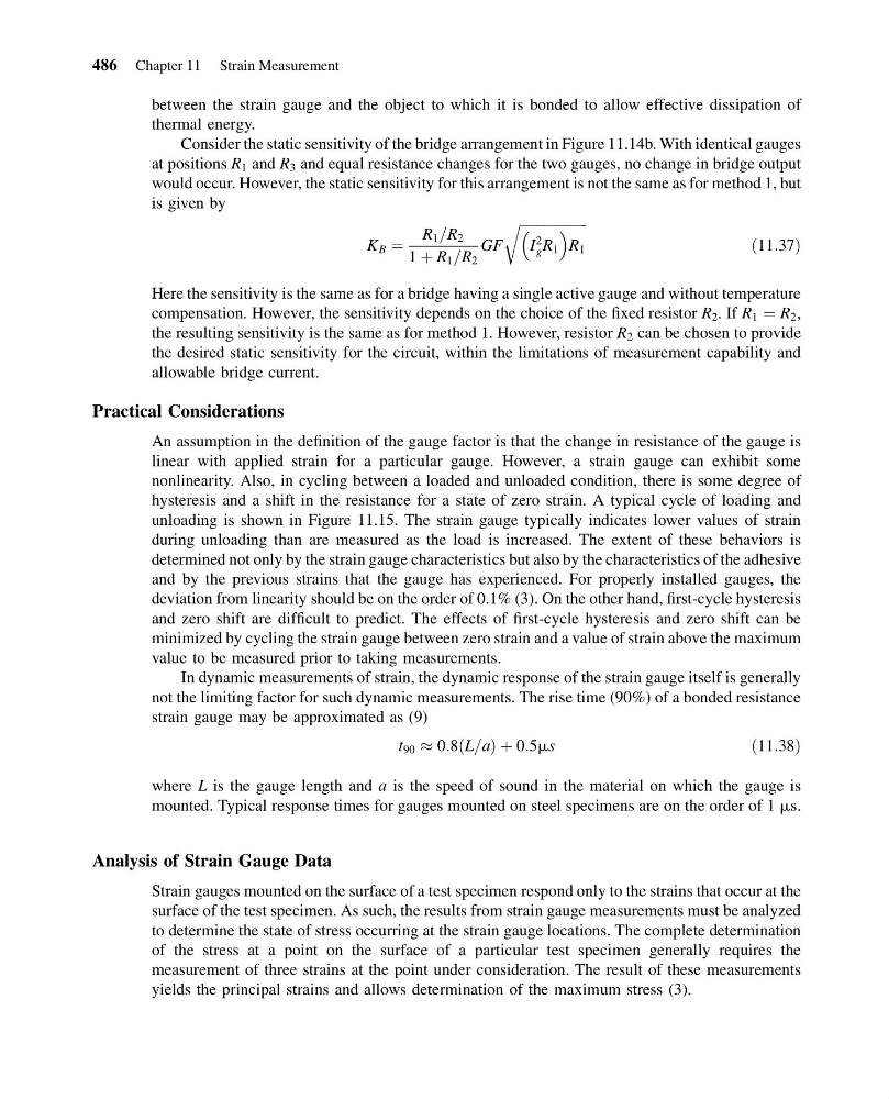
Consider the static sensitivity of the bridge arrangement in Figure 11.14b. With identical gauges
at positions R 1 and R 3 and equal resistance changes for the two gauges, no change in bridge output
would occur. However, the static sensitivity for this arrangement is not the same as for method 1, but
is given by
K B ¼
R 1 =R 2
1 þ R 1 =R 2
GF
ffiffiffiffiffiffiffiffiffiffiffiffiffiffiffiffiffiffiffi ffi
I
2
g R 1
R 1
r
ð11:37Þ
Here the sensitivity is the same as for a bridge having a single active gauge and without temperature
compensation. However, the sensitivity depends on the choice of the fixed resistor R 2 . If R 1 ¼ R 2 ,
the resulting sensitivity is the same as for method 1. However, resistor R 2 can be chosen to provide
the desired static sensitivity for the circuit, within the limitations of measurement capability and
allowable bridge current.
Practical Considerations
An assumption in the definition of the gauge factor is that the change in resistance of the gauge is
linear with applied strain for a particular gauge. However, a strain gauge can exhibit some
nonlinearity. Also, in cycling between a loaded and unloaded condition, there is some degree of
hysteresis and a shift in the resistance for a state of zero strain. A typical cycle of loading and
unloading is shown in Figure 11.15. The strain gauge typically indicates lower values of strain
during unloading than are measured as the load is increased. The extent of these behaviors is
determined not only by the strain gauge characteristics but also by the characteristics of the adhesive
and by the previous strains that the gauge has experienced. For properly installed gauges, the
deviation from linearity should be on the order of 0.1% (3). On the other hand, first-cycle hysteresis
and zero shift are difficult to predict. The effects of first-cycle hysteresis and zero shift can be
minimized by cycling the strain gauge between zero strain and a value of strain above the maximum
value to be measured prior to taking measurements.
In dynamic measurements of strain, the dynamic response of the strain gauge itself is generally
not the limiting factor for such dynamic measurements. The rise time (90%) of a bonded resistance
strain gauge may be approximated as (9)
t 90 % 0:8 L=a
ð
Þþ0:5ms
ð11:38Þ
where L is the gauge length and a is the speed of sound in the material on which the gauge is
mounted. Typical response times for gauges mounted on steel specimens are on the order of 1 ms.
Analysis of Strain Gauge Data
Strain gauges mounted on the surface of a test specimen respond only to the strains that occur at the
surface of the test specimen. As such, the results from strain gauge measurements must be analyzed
to determine the state of stress occurring at the strain gauge locations. The complete determination
of the stress at a point on the surface of a particular test specimen generally requires the
measurement of three strains at the point under consideration. The result of these measurements
yields the principal strains and allows determination of the maximum stress (3).
486 Chapter 11 Strain Measurement
13:14:3 Page 486
between the strain gauge and the object to which it is bonded to allow effective dissipation of
thermal energy.
Consider the static sensitivity of the bridge arrangement in Figure 11.14b. With identical gauges
at positions R 1 and R 3 and equal resistance changes for the two gauges, no change in bridge output
would occur. However, the static sensitivity for this arrangement is not the same as for method 1, but
is given by
K B ¼
R 1 =R 2
1 þ R 1 =R 2
GF
ffiffiffiffiffiffiffiffiffiffiffiffiffiffiffiffiffiffiffi ffi
I
2
g R 1
R 1
r
ð11:37Þ
Here the sensitivity is the same as for a bridge having a single active gauge and without temperature
compensation. However, the sensitivity depends on the choice of the fixed resistor R 2 . If R 1 ¼ R 2 ,
the resulting sensitivity is the same as for method 1. However, resistor R 2 can be chosen to provide
the desired static sensitivity for the circuit, within the limitations of measurement capability and
allowable bridge current.
Practical Considerations
An assumption in the definition of the gauge factor is that the change in resistance of the gauge is
linear with applied strain for a particular gauge. However, a strain gauge can exhibit some
nonlinearity. Also, in cycling between a loaded and unloaded condition, there is some degree of
hysteresis and a shift in the resistance for a state of zero strain. A typical cycle of loading and
unloading is shown in Figure 11.15. The strain gauge typically indicates lower values of strain
during unloading than are measured as the load is increased. The extent of these behaviors is
determined not only by the strain gauge characteristics but also by the characteristics of the adhesive
and by the previous strains that the gauge has experienced. For properly installed gauges, the
deviation from linearity should be on the order of 0.1% (3). On the other hand, first-cycle hysteresis
and zero shift are difficult to predict. The effects of first-cycle hysteresis and zero shift can be
minimized by cycling the strain gauge between zero strain and a value of strain above the maximum
value to be measured prior to taking measurements.
In dynamic measurements of strain, the dynamic response of the strain gauge itself is generally
not the limiting factor for such dynamic measurements. The rise time (90%) of a bonded resistance
strain gauge may be approximated as (9)
t 90 % 0:8 L=a
ð
Þþ0:5ms
ð11:38Þ
where L is the gauge length and a is the speed of sound in the material on which the gauge is
mounted. Typical response times for gauges mounted on steel specimens are on the order of 1 ms.
Analysis of Strain Gauge Data
Strain gauges mounted on the surface of a test specimen respond only to the strains that occur at the
surface of the test specimen. As such, the results from strain gauge measurements must be analyzed
to determine the state of stress occurring at the strain gauge locations. The complete determination
of the stress at a point on the surface of a particular test specimen generally requires the
measurement of three strains at the point under consideration. The result of these measurements
yields the principal strains and allows determination of the maximum stress (3).
486 Chapter 11 Strain Measurement