

E1C11 09/14/2010
13:14:3 Page 487
The multiple-element strain gauges used to measure more than one strain at a point are called
strain gauge rosettes. An example of a two-element rosette is shown in Figure 11.16. For general
measurements of strain and stress, commercially available strain rosettes can be chosen that have a
pattern of multiple-direction gauges that is compatible with the specific nature of the particular
+1000
0
+2000
+3000
+4000
+5000
Applied strain level in microstrain
Applied strain level in microstrain
R/R
o (µΩ/Ω)
–2500
0
+2500
+5000
+7500
+10,000
+12,500
+15,000
+17,500
+20,000
+22,500
1
+25,000
ST cycle
+1000
0
+2000
+3000
+4000
+5000
+6000
R/R
o (µΩ/Ω)
0
+1000
+2000
+3000
+4000
+5000
+6000
+7000
1ST cycle
+1000
0
+2000
+3000
+4000
+5000
+6000
5TH cycle
(There were 3 additional
cycles to 6000 microstrain)
+1000
0
+2000
+3000
6TH cycle
+1000
0
+2000
+3000
+4000
+5000
2ND cycle
+1000
0
+2000
+3000
+4000
+5000
3RD cycle
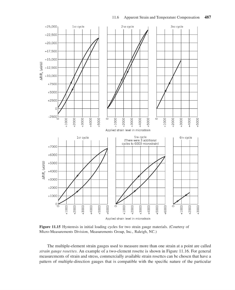
Figure 11.15 Hysteresis in initial loading cycles for two strain gauge materials. (Courtesy of
Micro-Measurements Division, Measurements Group, Inc., Raleigh, NC.)
11.6 Apparent Strain and Temperature Compensation 487
13:14:3 Page 487
The multiple-element strain gauges used to measure more than one strain at a point are called
strain gauge rosettes. An example of a two-element rosette is shown in Figure 11.16. For general
measurements of strain and stress, commercially available strain rosettes can be chosen that have a
pattern of multiple-direction gauges that is compatible with the specific nature of the particular
+1000
0
+2000
+3000
+4000
+5000
Applied strain level in microstrain
Applied strain level in microstrain
R/R
o (µΩ/Ω)
–2500
0
+2500
+5000
+7500
+10,000
+12,500
+15,000
+17,500
+20,000
+22,500
1
+25,000
ST cycle
+1000
0
+2000
+3000
+4000
+5000
+6000
R/R
o (µΩ/Ω)
0
+1000
+2000
+3000
+4000
+5000
+6000
+7000
1ST cycle
+1000
0
+2000
+3000
+4000
+5000
+6000
5TH cycle
(There were 3 additional
cycles to 6000 microstrain)
+1000
0
+2000
+3000
6TH cycle
+1000
0
+2000
+3000
+4000
+5000
2ND cycle
+1000
0
+2000
+3000
+4000
+5000
3RD cycle
Figure 11.15 Hysteresis in initial loading cycles for two strain gauge materials. (Courtesy of
Micro-Measurements Division, Measurements Group, Inc., Raleigh, NC.)
11.6 Apparent Strain and Temperature Compensation 487