

E1C11 09/14/2010
13:14:3 Page 485
to adjacent arms of a Wheatstone bridge, they will provide temperature compensation for each
other.
Looking back, the arrangement in Figure 11.13 does not provide temperature compensation, as
gauges 1 and 4 are on opposite bridge arms. However, temperature compensation could be provided
for that installation by having two additional strain gauges that are at the same temperature as gauges
1 and 4 and occupy arms 2 and 3 of the bridge.
Bridge Static Sensitivity
The static sensitivity of the bridge arrangement in Figure 11.14a (method 1) is
K B ¼
E 0
e
¼ E i
R 1 R 2
R 1 þ R 2
ð
Þ
2
GF
ð11:35Þ
and with E i ¼ 2R g
À
Á I g and R g ¼ R 1 ¼ R 2 , the static sensitivity may be expressed in the terms of the
current flowing through the gauge, I g
À Á
, as
K B ¼
1
2
GF
ffiffiffiffiffiffiffiffiffiffiffiffiffiffiffiffiffiffiffi ffi
I
2
g R 1
R 1
r
ð11:36Þ
Note that I
2
g R g is the power dissipated in the strain gauge as a result of the bridge current.
Excessive power dissipation in the gauge would cause temperature changes and introduce
uncertainty into a strain measurement. These effects can be minimized by good thermal coupling
E i
F N
F N
R 3
R 4
R 2
(a)
( b)
1
d
o
h
t
e
M
Method 2
A c t i v e
C o m
p e n s a t i n g
E o
R 1
E i
Active gauge
Test specimen
Compensating
gauge
Same
material
and
temperature
R 3
R 4
R 2
A c t i v e
C o m
p e n s a t i n g
E o
R 1
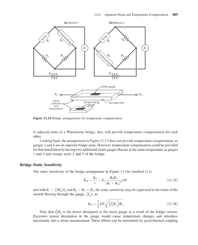
Figure 11.14 Bridge arrangements for temperature compensation.
11.6 Apparent Strain and Temperature Compensation 485
13:14:3 Page 485
to adjacent arms of a Wheatstone bridge, they will provide temperature compensation for each
other.
Looking back, the arrangement in Figure 11.13 does not provide temperature compensation, as
gauges 1 and 4 are on opposite bridge arms. However, temperature compensation could be provided
for that installation by having two additional strain gauges that are at the same temperature as gauges
1 and 4 and occupy arms 2 and 3 of the bridge.
Bridge Static Sensitivity
The static sensitivity of the bridge arrangement in Figure 11.14a (method 1) is
K B ¼
E 0
e
¼ E i
R 1 R 2
R 1 þ R 2
ð
Þ
2
GF
ð11:35Þ
and with E i ¼ 2R g
À
Á I g and R g ¼ R 1 ¼ R 2 , the static sensitivity may be expressed in the terms of the
current flowing through the gauge, I g
À Á
, as
K B ¼
1
2
GF
ffiffiffiffiffiffiffiffiffiffiffiffiffiffiffiffiffiffiffi ffi
I
2
g R 1
R 1
r
ð11:36Þ
Note that I
2
g R g is the power dissipated in the strain gauge as a result of the bridge current.
Excessive power dissipation in the gauge would cause temperature changes and introduce
uncertainty into a strain measurement. These effects can be minimized by good thermal coupling
E i
F N
F N
R 3
R 4
R 2
(a)
( b)
1
d
o
h
t
e
M
Method 2
A c t i v e
C o m
p e n s a t i n g
E o
R 1
E i
Active gauge
Test specimen
Compensating
gauge
Same
material
and
temperature
R 3
R 4
R 2
A c t i v e
C o m
p e n s a t i n g
E o
R 1
Figure 11.14 Bridge arrangements for temperature compensation.
11.6 Apparent Strain and Temperature Compensation 485