

E1C11 09/14/2010
13:14:3 Page 484
Equation 11.22,
dE 0 ¼ E i
GF e 1 À e 2
ð
Þ
4
¼ E i
GFe a
4
ð11:34Þ
where e 1 ¼ e a þ e T and e 2 ¼ e T (e T refers to the temperature-induced apparent strain). Under this
condition, the output value is not affected by changes in temperature. The result is the same if the
compensating gauge is mounted in arm 3 instead, as shown in Figure 11.14b. Furthermore, any two
active gauges mounted on adjacent bridge arms compensate for temperature changes.
Since this relationship holds in general, we can state that as long as two gauges, which are
mounted to a specimen or to similar specimens, remain at the same temperature and are connected
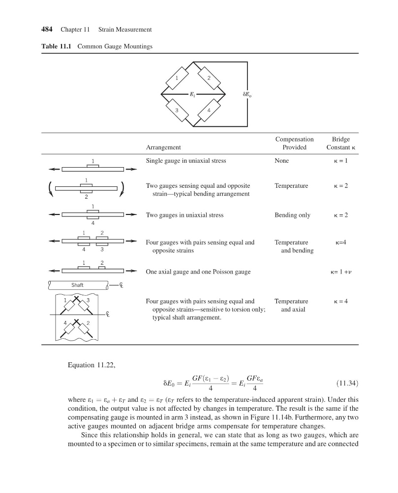
Table 11.1 Common Gauge Mountings
δE o
E i
1
2
3
4
Arrangement
Compensation
Provided
Bridge
Constant k
1
1
2
1
4
1
4
2
3
1
2
1
Shaft
L
C
L
C
3
4
2
Single gauge in uniaxial stress
None
k = 1
Two gauges sensing equal and opposite
strain—typical bending arrangement
Temperature
k = 2
Two gauges in uniaxial stress
Bending only
k = 2
Four gauges with pairs sensing equal and
opposite strains
Temperature
and bending
k=4
One axial gauge and one Poisson gauge
k= 1 +n
Four gauges with pairs sensing equal and
opposite strains—sensitive to torsion only;
typical shaft arrangement.
Temperature
and axial
k = 4
484 Chapter 11 Strain Measurement
13:14:3 Page 484
Equation 11.22,
dE 0 ¼ E i
GF e 1 À e 2
ð
Þ
4
¼ E i
GFe a
4
ð11:34Þ
where e 1 ¼ e a þ e T and e 2 ¼ e T (e T refers to the temperature-induced apparent strain). Under this
condition, the output value is not affected by changes in temperature. The result is the same if the
compensating gauge is mounted in arm 3 instead, as shown in Figure 11.14b. Furthermore, any two
active gauges mounted on adjacent bridge arms compensate for temperature changes.
Since this relationship holds in general, we can state that as long as two gauges, which are
mounted to a specimen or to similar specimens, remain at the same temperature and are connected
Table 11.1 Common Gauge Mountings
δE o
E i
1
2
3
4
Arrangement
Compensation
Provided
Bridge
Constant k
1
1
2
1
4
1
4
2
3
1
2
1
Shaft
L
C
L
C
3
4
2
Single gauge in uniaxial stress
None
k = 1
Two gauges sensing equal and opposite
strain—typical bending arrangement
Temperature
k = 2
Two gauges in uniaxial stress
Bending only
k = 2
Four gauges with pairs sensing equal and
opposite strains
Temperature
and bending
k=4
One axial gauge and one Poisson gauge
k= 1 +n
Four gauges with pairs sensing equal and
opposite strains—sensitive to torsion only;
typical shaft arrangement.
Temperature
and axial
k = 4
484 Chapter 11 Strain Measurement