

E1C11 09/14/2010
13:14:2 Page 477
reduces to
dE o
E i
¼
dR=R
4 þ 2 dR=R
ð
Þ
%
dR=R
4
ð11:14Þ
under the assumption that dR=R ( 1. This simplified form of Equation 6.15 is suitable for all but
those measurements that demand the highest accuracy, and is valid for values of dR=R ( 1. Using
the relationship from Equation 11.11 that dR=R ¼ GFe,
dE o
E i
¼
GFe
4 þ 2GFe
%
GFe
4
ð11:15Þ
Equations 11.14 and 11.15 yield two practical equations for strain gauge measurements using a
single gauge in a Wheatstone bridge.
The Wheatstone bridge has several distinct advantages for use with electrical resistance strain
gauges. The bridge may be balanced by changing the resistance of one arm of the bridge. Therefore,
once the gauge is mounted in place on the test specimen under a condition of zero loading, the output
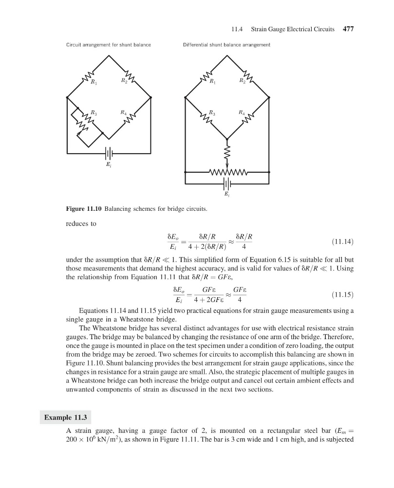
from the bridge may be zeroed. Two schemes for circuits to accomplish this balancing are shown in
Figure 11.10. Shunt balancing provides the best arrangement for strain gauge applications, since the
changes in resistance for a strain gauge are small. Also, the strategic placement of multiple gauges in
a Wheatstone bridge can both increase the bridge output and cancel out certain ambient effects and
unwanted components of strain as discussed in the next two sections.
Example 11.3
A strain gauge, having a gauge factor of 2, is mounted on a rectangular steel bar (E m ¼
200 Â 10
6 kN=m
2 ), as shown in Figure 11.11. The bar is 3 cm wide and 1 cm high, and is subjected
Circuit arrangement for shunt balance
Differential shunt balance arrangement
E i
R 3
R 4
R 2
R 1
E i
R 3
R 4
R 2
R 1
Figure 11.10 Balancing schemes for bridge circuits.
11.4 Strain Gauge Electrical Circuits 477
13:14:2 Page 477
reduces to
dE o
E i
¼
dR=R
4 þ 2 dR=R
ð
Þ
%
dR=R
4
ð11:14Þ
under the assumption that dR=R ( 1. This simplified form of Equation 6.15 is suitable for all but
those measurements that demand the highest accuracy, and is valid for values of dR=R ( 1. Using
the relationship from Equation 11.11 that dR=R ¼ GFe,
dE o
E i
¼
GFe
4 þ 2GFe
%
GFe
4
ð11:15Þ
Equations 11.14 and 11.15 yield two practical equations for strain gauge measurements using a
single gauge in a Wheatstone bridge.
The Wheatstone bridge has several distinct advantages for use with electrical resistance strain
gauges. The bridge may be balanced by changing the resistance of one arm of the bridge. Therefore,
once the gauge is mounted in place on the test specimen under a condition of zero loading, the output
from the bridge may be zeroed. Two schemes for circuits to accomplish this balancing are shown in
Figure 11.10. Shunt balancing provides the best arrangement for strain gauge applications, since the
changes in resistance for a strain gauge are small. Also, the strategic placement of multiple gauges in
a Wheatstone bridge can both increase the bridge output and cancel out certain ambient effects and
unwanted components of strain as discussed in the next two sections.
Example 11.3
A strain gauge, having a gauge factor of 2, is mounted on a rectangular steel bar (E m ¼
200 Â 10
6 kN=m
2 ), as shown in Figure 11.11. The bar is 3 cm wide and 1 cm high, and is subjected
Circuit arrangement for shunt balance
Differential shunt balance arrangement
E i
R 3
R 4
R 2
R 1
E i
R 3
R 4
R 2
R 1
Figure 11.10 Balancing schemes for bridge circuits.
11.4 Strain Gauge Electrical Circuits 477