

E1C11 09/14/2010
13:14:2 Page 476
lengths, silicon semiconductor strain gauge technology provides for the construction of very small
transducers. For example, flush-mount pressure transducers having diameters of less than 8 mm
provide pressure measurements up to 15,000 psi, with excellent frequency response characteristics.
However, silicone diaphragm pressure transducers require special procedures for measuring in
liquid environments such as deposition of a thin film of next material over the silicone diaphragm.
Semiconductor strain gauges are somewhat limited in the maximum strain that they can measure,
approximately 5000 me for tension, but larger in compression. Because of the possibility of an
inherent sensitivity to temperature, careful consideration must be given to each application to
provide appropriate temperature compensation or correction. Temperature effects can result, for a
particular measurement, in zero drift for the duration of a measurement.
11.4 STRAIN GAUGE ELECTRICAL CIRCUITS
A Wheatstone bridge is generally used to detect the small changes in resistance that are the output
of a strain gauge measurement circuit. A typical strain gauge measuring installation on a steel
specimen has a sensitivity of 10
À6
V/(kN m
2 ). As such, a high-sensitivity device such as a
Wheatstone bridge is desirable for measuring resistance changes for strain gauges. The fundamental
relationships for the analysis of such bridge circuits are discussed in Chapter 6. Equipment is
commercially available that can measure changes in gauge resistance of less than 0.0005 V
(0.000001 me).
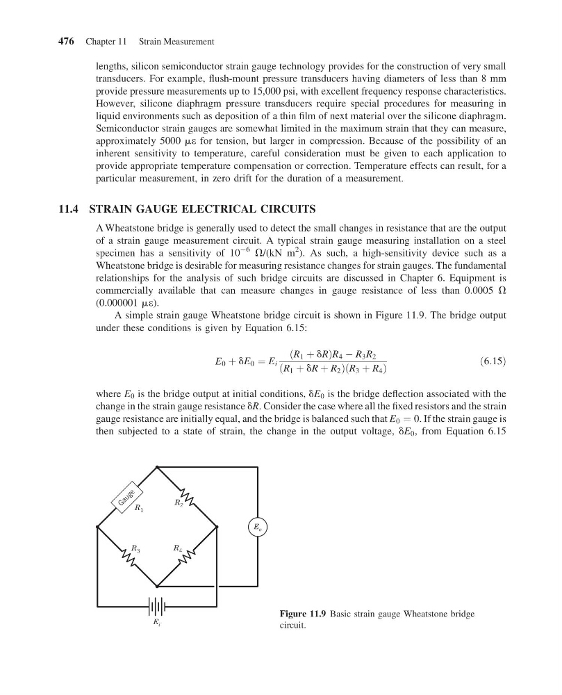
A simple strain gauge Wheatstone bridge circuit is shown in Figure 11.9. The bridge output
under these conditions is given by Equation 6.15:
E 0 þ dE 0 ¼ E i
R 1 þ dR
ð
Þ R 4 À R 3 R 2
R 1 þ dR þ R 2
ð
ÞR 3 þ R 4
ð
Þ
ð6:15Þ
where E 0 is the bridge output at initial conditions, dE 0 is the bridge deflection associated with the
change in the strain gauge resistance dR. Consider the case where all the fixed resistors and the strain
gauge resistance are initially equal, and the bridge is balanced such that E 0 ¼ 0. If the strain gauge is
then subjected to a state of strain, the change in the output voltage, dE 0 , from Equation 6.15
E i
R 3
R 4
R 2
G a u g e
E o
R 1
Figure 11.9 Basic strain gauge Wheatstone bridge
circuit.
476 Chapter 11 Strain Measurement
13:14:2 Page 476
lengths, silicon semiconductor strain gauge technology provides for the construction of very small
transducers. For example, flush-mount pressure transducers having diameters of less than 8 mm
provide pressure measurements up to 15,000 psi, with excellent frequency response characteristics.
However, silicone diaphragm pressure transducers require special procedures for measuring in
liquid environments such as deposition of a thin film of next material over the silicone diaphragm.
Semiconductor strain gauges are somewhat limited in the maximum strain that they can measure,
approximately 5000 me for tension, but larger in compression. Because of the possibility of an
inherent sensitivity to temperature, careful consideration must be given to each application to
provide appropriate temperature compensation or correction. Temperature effects can result, for a
particular measurement, in zero drift for the duration of a measurement.
11.4 STRAIN GAUGE ELECTRICAL CIRCUITS
A Wheatstone bridge is generally used to detect the small changes in resistance that are the output
of a strain gauge measurement circuit. A typical strain gauge measuring installation on a steel
specimen has a sensitivity of 10
À6
V/(kN m
2 ). As such, a high-sensitivity device such as a
Wheatstone bridge is desirable for measuring resistance changes for strain gauges. The fundamental
relationships for the analysis of such bridge circuits are discussed in Chapter 6. Equipment is
commercially available that can measure changes in gauge resistance of less than 0.0005 V
(0.000001 me).
A simple strain gauge Wheatstone bridge circuit is shown in Figure 11.9. The bridge output
under these conditions is given by Equation 6.15:
E 0 þ dE 0 ¼ E i
R 1 þ dR
ð
Þ R 4 À R 3 R 2
R 1 þ dR þ R 2
ð
ÞR 3 þ R 4
ð
Þ
ð6:15Þ
where E 0 is the bridge output at initial conditions, dE 0 is the bridge deflection associated with the
change in the strain gauge resistance dR. Consider the case where all the fixed resistors and the strain
gauge resistance are initially equal, and the bridge is balanced such that E 0 ¼ 0. If the strain gauge is
then subjected to a state of strain, the change in the output voltage, dE 0 , from Equation 6.15
E i
R 3
R 4
R 2
G a u g e
E o
R 1
Figure 11.9 Basic strain gauge Wheatstone bridge
circuit.
476 Chapter 11 Strain Measurement