

E1C11 09/14/2010
13:14:2 Page 472
Strain Gauge Construction and Bonding
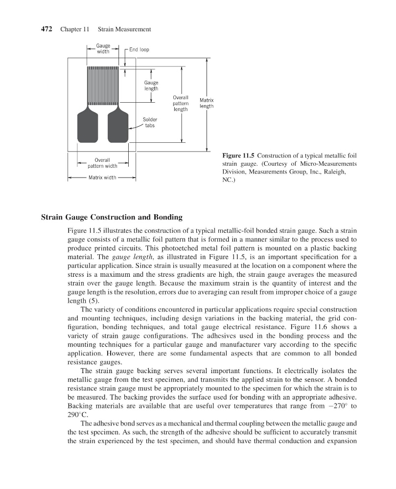
Figure 11.5 illustrates the construction of a typical metallic-foil bonded strain gauge. Such a strain
gauge consists of a metallic foil pattern that is formed in a manner similar to the process used to
produce printed circuits. This photoetched metal foil pattern is mounted on a plastic backing
material. The gauge length, as illustrated in Figure 11.5, is an important specification for a
particular application. Since strain is usually measured at the location on a component where the
stress is a maximum and the stress gradients are high, the strain gauge averages the measured
strain over the gauge length. Because the maximum strain is the quantity of interest and the
gauge length is the resolution, errors due to averaging can result from improper choice of a gauge
length (5).
The variety of conditions encountered in particular applications require special construction
and mounting techniques, including design variations in the backing material, the grid configuration, bonding techniques, and total gauge electrical resistance. Figure 11.6 shows a
variety of strain gauge configurations. The adhesives used in the bonding process and the
mounting techniques for a particular gauge and manufacturer vary according to the specific
application. However, there are some fundamental aspects that are common to all bonded
resistance gauges.
The strain gauge backing serves several important functions. It electrically isolates the
metallic gauge from the test specimen, and transmits the applied strain to the sensor. A bonded
resistance strain gauge must be appropriately mounted to the specimen for which the strain is to
be measured. The backing provides the surface used for bonding with an appropriate adhesive.
Backing materials are available that are useful over temperatures that range from À270
to
290
C.
The adhesive bond serves as a mechanical and thermal coupling between the metallic gauge and
the test specimen. As such, the strength of the adhesive should be sufficient to accurately transmit
the strain experienced by the test specimen, and should have thermal conduction and expansion
Solder
tabs
End loop
Overall
pattern width
Matrix
length
Overall
pattern
length
Gauge
length
Matrix width
Gauge
width
Figure 11.5 Construction of a typical metallic foil
strain gauge. (Courtesy of Micro-Measurements
Division, Measurements Group, Inc., Raleigh,
NC.)
472 Chapter 11 Strain Measurement
13:14:2 Page 472
Strain Gauge Construction and Bonding
Figure 11.5 illustrates the construction of a typical metallic-foil bonded strain gauge. Such a strain
gauge consists of a metallic foil pattern that is formed in a manner similar to the process used to
produce printed circuits. This photoetched metal foil pattern is mounted on a plastic backing
material. The gauge length, as illustrated in Figure 11.5, is an important specification for a
particular application. Since strain is usually measured at the location on a component where the
stress is a maximum and the stress gradients are high, the strain gauge averages the measured
strain over the gauge length. Because the maximum strain is the quantity of interest and the
gauge length is the resolution, errors due to averaging can result from improper choice of a gauge
length (5).
The variety of conditions encountered in particular applications require special construction
and mounting techniques, including design variations in the backing material, the grid configuration, bonding techniques, and total gauge electrical resistance. Figure 11.6 shows a
variety of strain gauge configurations. The adhesives used in the bonding process and the
mounting techniques for a particular gauge and manufacturer vary according to the specific
application. However, there are some fundamental aspects that are common to all bonded
resistance gauges.
The strain gauge backing serves several important functions. It electrically isolates the
metallic gauge from the test specimen, and transmits the applied strain to the sensor. A bonded
resistance strain gauge must be appropriately mounted to the specimen for which the strain is to
be measured. The backing provides the surface used for bonding with an appropriate adhesive.
Backing materials are available that are useful over temperatures that range from À270
to
290
C.
The adhesive bond serves as a mechanical and thermal coupling between the metallic gauge and
the test specimen. As such, the strength of the adhesive should be sufficient to accurately transmit
the strain experienced by the test specimen, and should have thermal conduction and expansion
Solder
tabs
End loop
Overall
pattern width
Matrix
length
Overall
pattern
length
Gauge
length
Matrix width
Gauge
width
Figure 11.5 Construction of a typical metallic foil
strain gauge. (Courtesy of Micro-Measurements
Division, Measurements Group, Inc., Raleigh,
NC.)
472 Chapter 11 Strain Measurement