

E1C11 09/14/2010
13:14:2 Page 473
characteristics suitable for the application. If the adhesive shrinks or expands during the curing
process, apparent strain can be created in the gauge. A wide array of adhesives are available for
bonding strain gauges to a test specimen. Among these are epoxies, cellulose nitrate cement, and
ceramic-based cements.
Gauge Factor
The change in resistance of a strain gauge is normally expressed in terms of an empirically
determined parameter called the gauge factor (GF). For a particular strain gauge, the gauge factor is
supplied by the manufacturer. The gauge factor is defined as
GF
dR=R
dL=L
¼
dR=R
e a
ð11:11Þ
Relating this definition to Equation 11.10, we see that the gauge factor is dependent on the
Poisson ratio for the gauge material and its piezoresistivity. For metallic strain gauges, the Poisson
ratio is approximately 0.3 and the resulting gauge factor is $ 2.
The gauge factor represents the total change in resistance for a strain gauge, under a
calibration loading condition. The calibration loading condition generally creates a biaxial strain
field, and the lateral sensitivity of the gauge influences the measured result. Strictly speaking
then, the sensitivity to normal strain of the material used in the gauge and the gauge factor are not
the same. Generally gauge factors are measured in a biaxial strain field that results from the
deflection of a beam having a value of Poisson’s ratio of 0.285. Thus, for any other strain field
there is an error in strain indication due to the transverse sensitivity of the strain gauge. The
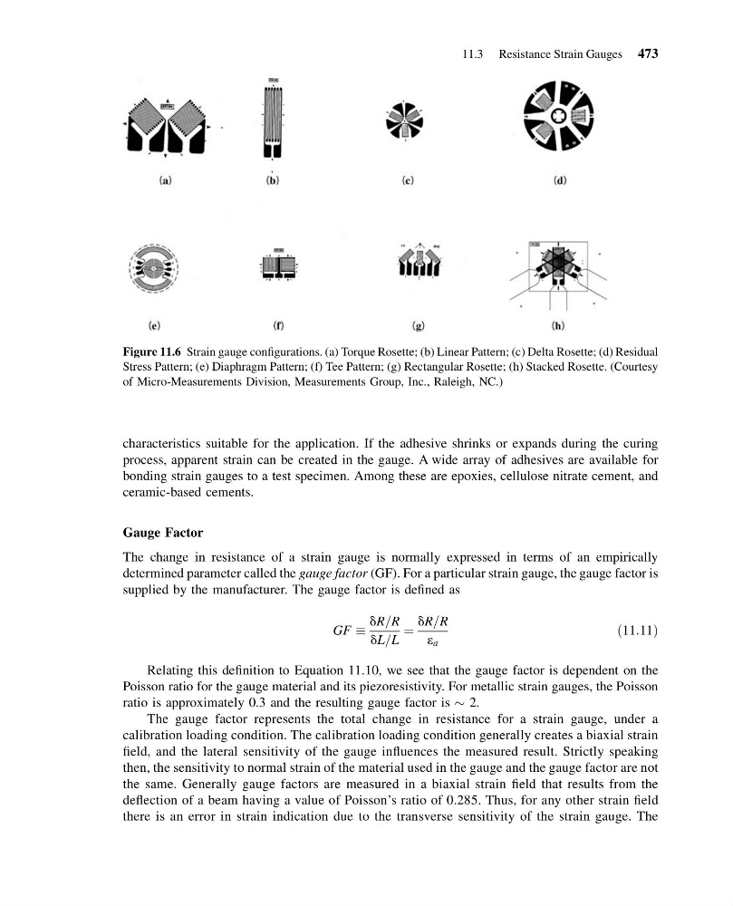
Figure 11.6 Strain gauge configurations. (a) Torque Rosette; (b) Linear Pattern; (c) Delta Rosette; (d) Residual
Stress Pattern; (e) Diaphragm Pattern; (f) Tee Pattern; (g) Rectangular Rosette; (h) Stacked Rosette. (Courtesy
of Micro-Measurements Division, Measurements Group, Inc., Raleigh, NC.)
11.3 Resistance Strain Gauges 473
13:14:2 Page 473
characteristics suitable for the application. If the adhesive shrinks or expands during the curing
process, apparent strain can be created in the gauge. A wide array of adhesives are available for
bonding strain gauges to a test specimen. Among these are epoxies, cellulose nitrate cement, and
ceramic-based cements.
Gauge Factor
The change in resistance of a strain gauge is normally expressed in terms of an empirically
determined parameter called the gauge factor (GF). For a particular strain gauge, the gauge factor is
supplied by the manufacturer. The gauge factor is defined as
GF
dR=R
dL=L
¼
dR=R
e a
ð11:11Þ
Relating this definition to Equation 11.10, we see that the gauge factor is dependent on the
Poisson ratio for the gauge material and its piezoresistivity. For metallic strain gauges, the Poisson
ratio is approximately 0.3 and the resulting gauge factor is $ 2.
The gauge factor represents the total change in resistance for a strain gauge, under a
calibration loading condition. The calibration loading condition generally creates a biaxial strain
field, and the lateral sensitivity of the gauge influences the measured result. Strictly speaking
then, the sensitivity to normal strain of the material used in the gauge and the gauge factor are not
the same. Generally gauge factors are measured in a biaxial strain field that results from the
deflection of a beam having a value of Poisson’s ratio of 0.285. Thus, for any other strain field
there is an error in strain indication due to the transverse sensitivity of the strain gauge. The
Figure 11.6 Strain gauge configurations. (a) Torque Rosette; (b) Linear Pattern; (c) Delta Rosette; (d) Residual
Stress Pattern; (e) Diaphragm Pattern; (f) Tee Pattern; (g) Rectangular Rosette; (h) Stacked Rosette. (Courtesy
of Micro-Measurements Division, Measurements Group, Inc., Raleigh, NC.)
11.3 Resistance Strain Gauges 473