

E1C10 09/14/2010
13:4:41 Page 456
Coriolis Flow Meter
The term ‘‘Coriolis flow meter’’ refers to the family of insertion meters that meter mass flow rate by
inducing a Coriolis acceleration on the flowing fluid and measuring the resulting developed force
(13). The developed force is directly related to the mass flow rate independent of the fluid properties.
The Coriolis effect was proposed by Gaspard de Coriolis (1792–1843) following his studies of
accelerations in rotating systems. Coriolis meters pass a fluid through a rotating or vibrating pipe
system to develop the Coriolis force. A number of methods to utilize this effect have been proposed
since the first U.S. patent for a Coriolis effect meter was issued in 1947. This family of meters has
seen steady growth in market share since the mid-1980s.
In the most common scheme for commercially available units, the pipe flow is diverted from the
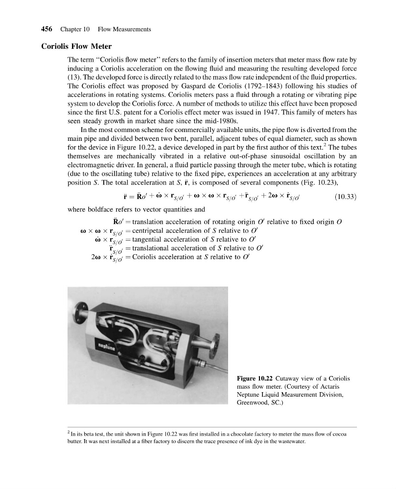
main pipe and divided between two bent, parallel, adjacent tubes of equal diameter, such as shown
for the device in Figure 10.22, a device developed in part by the first author of this text.
2 The tubes
themselves are mechanically vibrated in a relative out-of-phase sinusoidal oscillation by an
electromagnetic driver. In general, a fluid particle passing through the meter tube, which is rotating
(due to the oscillating tube) relative to the fixed pipe, experiences an acceleration at any arbitrary
position S. The total acceleration at S, r
€, is composed of several components (Fig. 10.23),
r € ¼ R € o
0 þ _
v  r S=O
0 þ v  v  r S=O
0 þ€ r S=O
0 þ 2v  _
r S=O
0
ð10:33Þ
where boldface refers to vector quantities and
R € o
0
¼ translation acceleration of rotating origin O
0 relative to fixed origin O
v  v  r S=O
0 ¼ centripetal acceleration of S relative to O
0
_
v  r S=O
0 ¼ tangential acceleration of S relative to O
0
€ r S=O
0 ¼ translational acceleration of S relative to O
0
2v  _
r S=O
0 ¼ Coriolis acceleration at S relative to O
0
Figure 10.22 Cutaway view of a Coriolis
mass flow meter. (Courtesy of Actaris
Neptune Liquid Measurement Division,
Greenwood, SC.)
2 In its beta test, the unit shown in Figure 10.22 was first installed in a chocolate factory to meter the mass flow of cocoa
butter. It was next installed at a fiber factory to discern the trace presence of ink dye in the wastewater.
456 Chapter 10 Flow Measurements
13:4:41 Page 456
Coriolis Flow Meter
The term ‘‘Coriolis flow meter’’ refers to the family of insertion meters that meter mass flow rate by
inducing a Coriolis acceleration on the flowing fluid and measuring the resulting developed force
(13). The developed force is directly related to the mass flow rate independent of the fluid properties.
The Coriolis effect was proposed by Gaspard de Coriolis (1792–1843) following his studies of
accelerations in rotating systems. Coriolis meters pass a fluid through a rotating or vibrating pipe
system to develop the Coriolis force. A number of methods to utilize this effect have been proposed
since the first U.S. patent for a Coriolis effect meter was issued in 1947. This family of meters has
seen steady growth in market share since the mid-1980s.
In the most common scheme for commercially available units, the pipe flow is diverted from the
main pipe and divided between two bent, parallel, adjacent tubes of equal diameter, such as shown
for the device in Figure 10.22, a device developed in part by the first author of this text.
2 The tubes
themselves are mechanically vibrated in a relative out-of-phase sinusoidal oscillation by an
electromagnetic driver. In general, a fluid particle passing through the meter tube, which is rotating
(due to the oscillating tube) relative to the fixed pipe, experiences an acceleration at any arbitrary
position S. The total acceleration at S, r
€, is composed of several components (Fig. 10.23),
r € ¼ R € o
0 þ _
v  r S=O
0 þ v  v  r S=O
0 þ€ r S=O
0 þ 2v  _
r S=O
0
ð10:33Þ
where boldface refers to vector quantities and
R € o
0
¼ translation acceleration of rotating origin O
0 relative to fixed origin O
v  v  r S=O
0 ¼ centripetal acceleration of S relative to O
0
_
v  r S=O
0 ¼ tangential acceleration of S relative to O
0
€ r S=O
0 ¼ translational acceleration of S relative to O
0
2v  _
r S=O
0 ¼ Coriolis acceleration at S relative to O
0
Figure 10.22 Cutaway view of a Coriolis
mass flow meter. (Courtesy of Actaris
Neptune Liquid Measurement Division,
Greenwood, SC.)
2 In its beta test, the unit shown in Figure 10.22 was first installed in a chocolate factory to meter the mass flow of cocoa
butter. It was next installed at a fiber factory to discern the trace presence of ink dye in the wastewater.
456 Chapter 10 Flow Measurements