

E1C10 09/14/2010
13:4:40 Page 455
If the density of the metered fluid is known under the exact conditions of measurement, then
a direct estimate can be made based on volume flow rate measurements. But not all fluids have a
constant, known value of density (e.g., petroleum products, polymers, and cocoa butter), and many
processes are subject to significant changes in density. The direct measurement of mass flow rate is
desirable because it eliminates the uncertainties associated with estimating or measuring actual
density.
The difference between a meter that is sensitive to Q as opposed to _
m is not trivial. Prior to the
1970s, reliable commercial mass flow meters with sufficient accuracy to circumvent volume flow
rate corrections were generally not available, even though the basic principles and implementation
schemes for such meters had been understood in theory for several decades. United States patents
dating back to the 1940s record schemes for using heat transfer, Coriolis forces, and momentum
methods to infer mass flow rate directly.
Thermal Flow Meter
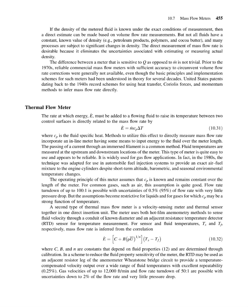
The rate at which energy, _
E, must be added to a flowing fluid to raise its temperature between two
control surfaces is directly related to the mass flow rate by
_
E ¼ _
mc p DT
ð10:31Þ
where c p is the fluid specific heat. Methods to utilize this effect to directly measure mass flow rate
incorporate an in-line meter having some means to input energy to the fluid over the meter length.
The passing of a current through an immersed filament is a common method. Fluid temperatures are
measured at the upstream and downstream locations of the meter. This type of meter is quite easy to
use and appears to be reliable. It is widely used for gas flow applications. In fact, in the 1980s, the
technique was adapted for use in automobile fuel injection systems to provide an exact air–fuel
mixture to the engine cylinders despite short-term altitude, barometric, and seasonal environmental
temperature changes.
The operating principle of this meter assumes that c p is known and remains constant over the
length of the meter. For common gases, such as air, this assumption is quite good. Flow rate
turndown of up to 100:1 is possible with uncertainties of 0.5% (95%) of flow rate with very little
pressure drop. But the assumptions become restrictive for liquids and for gases for which c p may be a
strong function of temperature.
A second type of thermal mass flow meter is a velocity-sensing meter and thermal sensor
together in one direct insertion unit. The meter uses both hot-film anemometry methods to sense
fluid velocity through a conduit of known diameter and an adjacent resistance temperature detector
(RTD) sensor for temperature measurement. For sensor and fluid temperatures, T s and T f ,
respectively, mass flow rate is inferred from the correlation
_
E ¼ C þ B rU
À Á 1=n
h
i
T s À T f
À
Á
ð10:32Þ
where C, B, and n are constants that depend on fluid properties (12) and are determined through
calibration. In a scheme to reduce the fluid property sensitivity of the meter, the RTD may be used as
an adjacent resistor leg of the anemometer Wheatstone bridge circuit to provide a temperaturecompensated velocity output over a wide range of fluid temperatures with excellent repeatability
(0.25%). Gas velocities of up to 12,000 ft/min and flow rate turndown of 50:1 are possible with
uncertainties down to 2% of the flow rate and very little pressure drop.
10.7 Mass Flow Meters 455
13:4:40 Page 455
If the density of the metered fluid is known under the exact conditions of measurement, then
a direct estimate can be made based on volume flow rate measurements. But not all fluids have a
constant, known value of density (e.g., petroleum products, polymers, and cocoa butter), and many
processes are subject to significant changes in density. The direct measurement of mass flow rate is
desirable because it eliminates the uncertainties associated with estimating or measuring actual
density.
The difference between a meter that is sensitive to Q as opposed to _
m is not trivial. Prior to the
1970s, reliable commercial mass flow meters with sufficient accuracy to circumvent volume flow
rate corrections were generally not available, even though the basic principles and implementation
schemes for such meters had been understood in theory for several decades. United States patents
dating back to the 1940s record schemes for using heat transfer, Coriolis forces, and momentum
methods to infer mass flow rate directly.
Thermal Flow Meter
The rate at which energy, _
E, must be added to a flowing fluid to raise its temperature between two
control surfaces is directly related to the mass flow rate by
_
E ¼ _
mc p DT
ð10:31Þ
where c p is the fluid specific heat. Methods to utilize this effect to directly measure mass flow rate
incorporate an in-line meter having some means to input energy to the fluid over the meter length.
The passing of a current through an immersed filament is a common method. Fluid temperatures are
measured at the upstream and downstream locations of the meter. This type of meter is quite easy to
use and appears to be reliable. It is widely used for gas flow applications. In fact, in the 1980s, the
technique was adapted for use in automobile fuel injection systems to provide an exact air–fuel
mixture to the engine cylinders despite short-term altitude, barometric, and seasonal environmental
temperature changes.
The operating principle of this meter assumes that c p is known and remains constant over the
length of the meter. For common gases, such as air, this assumption is quite good. Flow rate
turndown of up to 100:1 is possible with uncertainties of 0.5% (95%) of flow rate with very little
pressure drop. But the assumptions become restrictive for liquids and for gases for which c p may be a
strong function of temperature.
A second type of thermal mass flow meter is a velocity-sensing meter and thermal sensor
together in one direct insertion unit. The meter uses both hot-film anemometry methods to sense
fluid velocity through a conduit of known diameter and an adjacent resistance temperature detector
(RTD) sensor for temperature measurement. For sensor and fluid temperatures, T s and T f ,
respectively, mass flow rate is inferred from the correlation
_
E ¼ C þ B rU
À Á 1=n
h
i
T s À T f
À
Á
ð10:32Þ
where C, B, and n are constants that depend on fluid properties (12) and are determined through
calibration. In a scheme to reduce the fluid property sensitivity of the meter, the RTD may be used as
an adjacent resistor leg of the anemometer Wheatstone bridge circuit to provide a temperaturecompensated velocity output over a wide range of fluid temperatures with excellent repeatability
(0.25%). Gas velocities of up to 12,000 ft/min and flow rate turndown of 50:1 are possible with
uncertainties down to 2% of the flow rate and very little pressure drop.
10.7 Mass Flow Meters 455