

E1C10 09/14/2010
13:4:41 Page 457
with v the angular velocity of point S relative to O
0 . In these meters, the tubes are rotated but not
translated, so that the translational accelerations are zero. A fluid particle experiences forces due to
the remaining accelerations that cause equal and opposite reactions on the meter tube walls. The
Coriolis acceleration distinguishes itself by acting in a plane perpendicular to the tube axes and
develops a force gradient that creates a twisting motion or oscillating rotation about the tube plane.
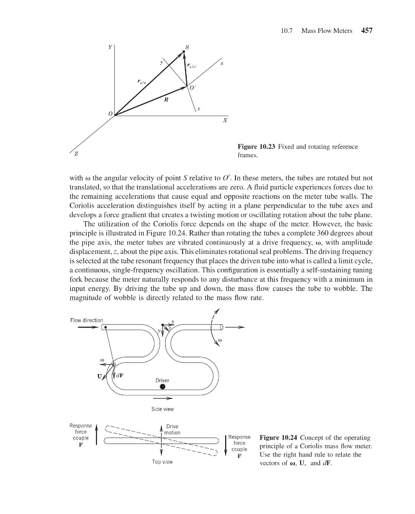
The utilization of the Coriolis force depends on the shape of the meter. However, the basic
principle is illustrated in Figure 10.24. Rather than rotating the tubes a complete 360 degrees about
the pipe axis, the meter tubes are vibrated continuously at a drive frequency, v, with amplitude
displacement, z, about the pipe axis. This eliminates rotational seal problems. The driving frequency
is selected at the tube resonant frequency that places the driven tube into what is called a limit cycle,
a continuous, single-frequency oscillation. This configuration is essentially a self-sustaining tuning
fork because the meter naturally responds to any disturbance at this frequency with a minimum in
input energy. By driving the tube up and down, the mass flow causes the tube to wobble. The
magnitude of wobble is directly related to the mass flow rate.
X
z
x
R
S
y
r s/o'
r s/o
O
O'
Y
Z
Figure 10.23 Fixed and rotating reference
frames.
Flow direction
U
Driver
dF
x
z
y
Side view
Response
force
couple
F
Response
force
couple
F
Top view
Drive
motion
ω
ω
Figure 10.24 Concept of the operating
principle of a Coriolis mass flow meter.
Use the right hand rule to relate the
vectors of v, U, and dF.
10.7 Mass Flow Meters 457
13:4:41 Page 457
with v the angular velocity of point S relative to O
0 . In these meters, the tubes are rotated but not
translated, so that the translational accelerations are zero. A fluid particle experiences forces due to
the remaining accelerations that cause equal and opposite reactions on the meter tube walls. The
Coriolis acceleration distinguishes itself by acting in a plane perpendicular to the tube axes and
develops a force gradient that creates a twisting motion or oscillating rotation about the tube plane.
The utilization of the Coriolis force depends on the shape of the meter. However, the basic
principle is illustrated in Figure 10.24. Rather than rotating the tubes a complete 360 degrees about
the pipe axis, the meter tubes are vibrated continuously at a drive frequency, v, with amplitude
displacement, z, about the pipe axis. This eliminates rotational seal problems. The driving frequency
is selected at the tube resonant frequency that places the driven tube into what is called a limit cycle,
a continuous, single-frequency oscillation. This configuration is essentially a self-sustaining tuning
fork because the meter naturally responds to any disturbance at this frequency with a minimum in
input energy. By driving the tube up and down, the mass flow causes the tube to wobble. The
magnitude of wobble is directly related to the mass flow rate.
X
z
x
R
S
y
r s/o'
r s/o
O
O'
Y
Z
Figure 10.23 Fixed and rotating reference
frames.
Flow direction
U
Driver
dF
x
z
y
Side view
Response
force
couple
F
Response
force
couple
F
Top view
Drive
motion
ω
ω
Figure 10.24 Concept of the operating
principle of a Coriolis mass flow meter.
Use the right hand rule to relate the
vectors of v, U, and dF.
10.7 Mass Flow Meters 457