

E1C10 09/14/2010
13:4:40 Page 452
In operation, the float rises to an equilibrium position. The height of this position increases with
flow velocity and, hence, flow rate. This flow rate is found by
Q ¼ UA a ðyÞ ¼ K 1 A a ðyÞ
ð 10:26Þ
where A a (y) is the annular area between the float and the tube, and K 1 is a meter constant. Both the
average velocity and the annular area depend on the height of the float in the tube. So the float’s
vertical position is a direct measure of flow rate, which can be read from a graduated scale,
electronically sensed with an optical cell, or detected magnetically. Floats with sharp edges are less
sensitive to fluid viscosity changes with temperature. A typical meter turndown is 10:1 with an
instrument systematic uncertainty of $2% (95%) of flow rate.
Turbine Meters
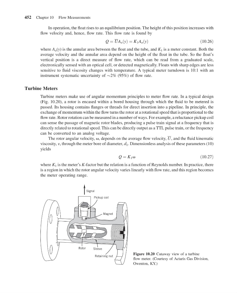
Turbine meters make use of angular momentum principles to meter flow rate. In a typical design
(Fig. 10.20), a rotor is encased within a bored housing through which the fluid to be metered is
passed. Its housing contains flanges or threads for direct insertion into a pipeline. In principle, the
exchange of momentum within the flow turns the rotor at a rotational speed that is proportional to the
flow rate. Rotor rotation can be measured in a number of ways. For example, a reluctance pickup coil
can sense the passage of magnetic rotor blades, producing a pulse train signal at a frequency that is
directly related to rotational speed. This can be directly output as a TTL pulse train, or the frequency
can be converted to an analog voltage.
The rotor angular velocity, v, depends on the average flow velocity, U , and the fluid kinematic
viscosity, n, through the meter bore of diameter, d 1 . Dimensionless analysis of these parameters (10)
yields
Q ¼ K 1 v
ð10:27Þ
where K 1 is the meter’s K-factor but the relation is a function of Reynolds number. In practice, there
is a region in which the rotor angular velocity varies linearly with flow rate, and this region becomes
the meter operating range.
Signal
Pickup coil
Magnet
Retaining nut
Sleeve
Rotor
Figure 10.20 Cutaway view of a turbine
flow meter. (Courtesy of Actaris Gas Division,
Owenton, KY.)
452 Chapter 10 Flow Measurements
13:4:40 Page 452
In operation, the float rises to an equilibrium position. The height of this position increases with
flow velocity and, hence, flow rate. This flow rate is found by
Q ¼ UA a ðyÞ ¼ K 1 A a ðyÞ
ð 10:26Þ
where A a (y) is the annular area between the float and the tube, and K 1 is a meter constant. Both the
average velocity and the annular area depend on the height of the float in the tube. So the float’s
vertical position is a direct measure of flow rate, which can be read from a graduated scale,
electronically sensed with an optical cell, or detected magnetically. Floats with sharp edges are less
sensitive to fluid viscosity changes with temperature. A typical meter turndown is 10:1 with an
instrument systematic uncertainty of $2% (95%) of flow rate.
Turbine Meters
Turbine meters make use of angular momentum principles to meter flow rate. In a typical design
(Fig. 10.20), a rotor is encased within a bored housing through which the fluid to be metered is
passed. Its housing contains flanges or threads for direct insertion into a pipeline. In principle, the
exchange of momentum within the flow turns the rotor at a rotational speed that is proportional to the
flow rate. Rotor rotation can be measured in a number of ways. For example, a reluctance pickup coil
can sense the passage of magnetic rotor blades, producing a pulse train signal at a frequency that is
directly related to rotational speed. This can be directly output as a TTL pulse train, or the frequency
can be converted to an analog voltage.
The rotor angular velocity, v, depends on the average flow velocity, U , and the fluid kinematic
viscosity, n, through the meter bore of diameter, d 1 . Dimensionless analysis of these parameters (10)
yields
Q ¼ K 1 v
ð10:27Þ
where K 1 is the meter’s K-factor but the relation is a function of Reynolds number. In practice, there
is a region in which the rotor angular velocity varies linearly with flow rate, and this region becomes
the meter operating range.
Signal
Pickup coil
Magnet
Retaining nut
Sleeve
Rotor
Figure 10.20 Cutaway view of a turbine
flow meter. (Courtesy of Actaris Gas Division,
Owenton, KY.)
452 Chapter 10 Flow Measurements