

E1C10 09/14/2010
13:4:39 Page 447
where a is the angle between the mean velocity vector and the magnetic flux vector, usually at
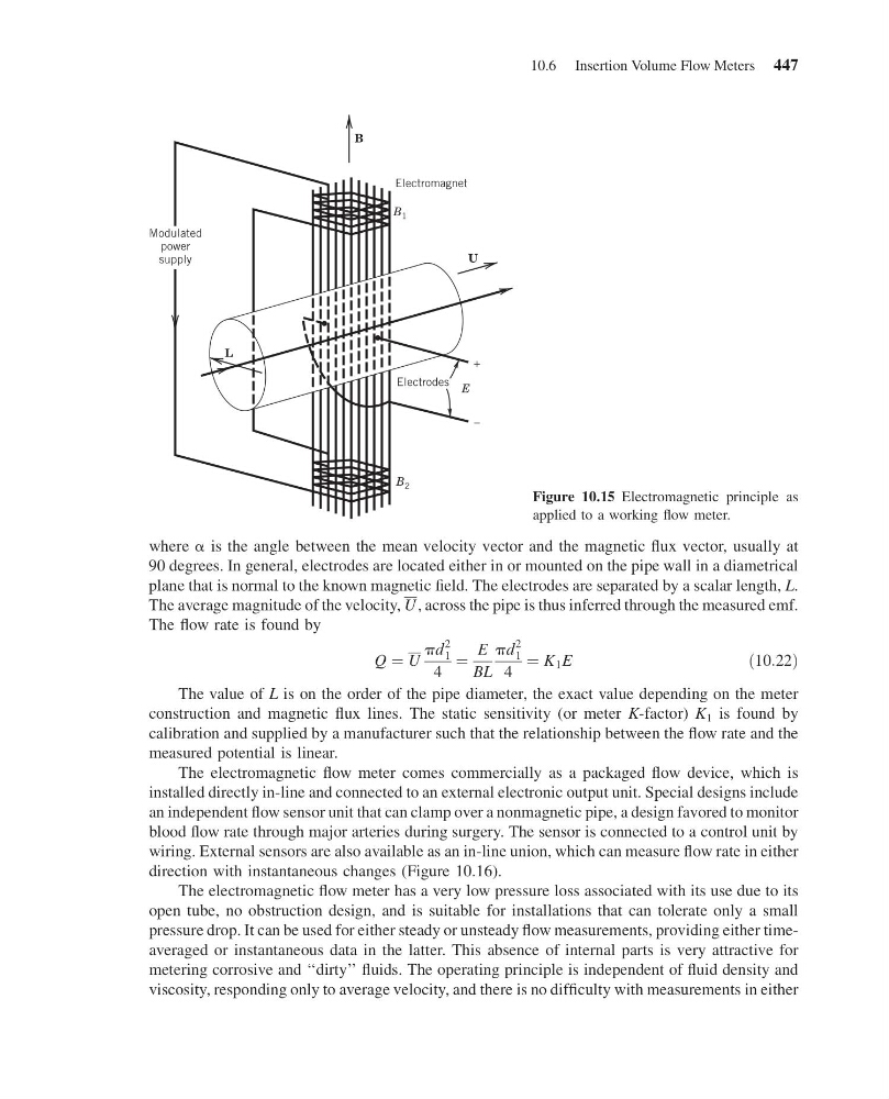
90 degrees. In general, electrodes are located either in or mounted on the pipe wall in a diametrical
plane that is normal to the known magnetic field. The electrodes are separated by a scalar length, L.
The average magnitude of the velocity, U , across the pipe is thus inferred through the measured emf.
The flow rate is found by
Q ¼ U
pd
2
1
4
¼
E
BL
pd
2
1
4
¼ K 1 E
ð10:22Þ
The value of L is on the order of the pipe diameter, the exact value depending on the meter
construction and magnetic flux lines. The static sensitivity (or meter K-factor) K 1 is found by
calibration and supplied by a manufacturer such that the relationship between the flow rate and the
measured potential is linear.
The electromagnetic flow meter comes commercially as a packaged flow device, which is
installed directly in-line and connected to an external electronic output unit. Special designs include
an independent flow sensor unit that can clamp over a nonmagnetic pipe, a design favored to monitor
blood flow rate through major arteries during surgery. The sensor is connected to a control unit by
wiring. External sensors are also available as an in-line union, which can measure flow rate in either
direction with instantaneous changes (Figure 10.16).
The electromagnetic flow meter has a very low pressure loss associated with its use due to its
open tube, no obstruction design, and is suitable for installations that can tolerate only a small
pressure drop. It can be used for either steady or unsteady flow measurements, providing either timeaveraged or instantaneous data in the latter. This absence of internal parts is very attractive for
metering corrosive and ‘‘dirty’’ fluids. The operating principle is independent of fluid density and
viscosity, responding only to average velocity, and there is no difficulty with measurements in either
Electromagnet
Electrodes
+
–
E
B 2
L
B 1
B
U
Modulated
power
supply
Figure 10.15 Electromagnetic principle as
applied to a working flow meter.
10.6 Insertion Volume Flow Meters 447
13:4:39 Page 447
where a is the angle between the mean velocity vector and the magnetic flux vector, usually at
90 degrees. In general, electrodes are located either in or mounted on the pipe wall in a diametrical
plane that is normal to the known magnetic field. The electrodes are separated by a scalar length, L.
The average magnitude of the velocity, U , across the pipe is thus inferred through the measured emf.
The flow rate is found by
Q ¼ U
pd
2
1
4
¼
E
BL
pd
2
1
4
¼ K 1 E
ð10:22Þ
The value of L is on the order of the pipe diameter, the exact value depending on the meter
construction and magnetic flux lines. The static sensitivity (or meter K-factor) K 1 is found by
calibration and supplied by a manufacturer such that the relationship between the flow rate and the
measured potential is linear.
The electromagnetic flow meter comes commercially as a packaged flow device, which is
installed directly in-line and connected to an external electronic output unit. Special designs include
an independent flow sensor unit that can clamp over a nonmagnetic pipe, a design favored to monitor
blood flow rate through major arteries during surgery. The sensor is connected to a control unit by
wiring. External sensors are also available as an in-line union, which can measure flow rate in either
direction with instantaneous changes (Figure 10.16).
The electromagnetic flow meter has a very low pressure loss associated with its use due to its
open tube, no obstruction design, and is suitable for installations that can tolerate only a small
pressure drop. It can be used for either steady or unsteady flow measurements, providing either timeaveraged or instantaneous data in the latter. This absence of internal parts is very attractive for
metering corrosive and ‘‘dirty’’ fluids. The operating principle is independent of fluid density and
viscosity, responding only to average velocity, and there is no difficulty with measurements in either
Electromagnet
Electrodes
+
–
E
B 2
L
B 1
B
U
Modulated
power
supply
Figure 10.15 Electromagnetic principle as
applied to a working flow meter.
10.6 Insertion Volume Flow Meters 447