

E1C10 09/14/2010
13:4:39 Page 446
Laminar flow elements offer some distinct advantages over other pressure differential meters.
These include (1) a high sensitivity even at low flow rates, (2) an ability to measure flow from either
meter direction, (3) a wide usable flow range, and (4) the ability to indicate an average flow rate in
pulsating flows. The instrument systematic uncertainty in flow rate determination is as low as 0.25%
(95%) of the flow rate. However, these meters are limited to clean fluids due to clogging potential.
All of the measured pressure drop remains a system pressure loss.
10.6 INSERTION VOLUME FLOW METERS
Dozens of volume flow meter types based on a number of different principles have been proposed,
developed, and sold commercially. A large group of meters is based on some phenomenon that
is actually sensitive to the average velocity across a control surface of known area, that is,
Q ¼ f U ; A
À
Á ¼ UA. Several of these designs are included in the discussion below. Another
common group, called positive displacement meters, actually measure parcels of a volume of
fluid per unit time, that is, Q ¼ f 8; t
ð Þ ¼ 8=t.
Electromagnetic Flow Meters
The operating principle of an electromagnetic flow meter (8) is based on the fundamental principle
that an electromotive force (emf) of electric potential, E, is induced in a conductor of length, L, which
moves with a velocity, U, through a magnetic field of magnetic flux, B. Simply, when an electrically
conductive liquid moves through a magnetic field, a voltage is induced in the liquid at a right angle to
the field. The voltage is detected by metal electrode sensors with the voltage magnitude and polarity
directly proportional to the volume flow rate and the flow direction, respectively. This physical
behavior was first recorded by Michael Faraday (1791–1867). In principle,
E ¼ U Â B Á L
ð10:21Þ
where symbols in bold face are vector quantities.
A practical utilization of the principle is shown in Figure 10.15. From Equation 10.21 the
magnitude of E is affected by the average velocity, U , as
E ¼ UBL sin a ¼ f U
À Á
p 1
p 2
A
A
A
A
p
a
T
p
a
T
e
g
n
a
l
F
e
g
n
Flow
a
l
F
Tube bundle
Tube bundle
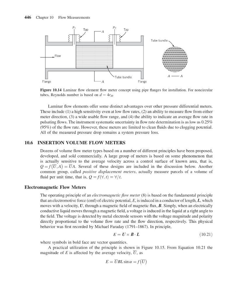
Figure 10.14 Laminar flow element flow meter concept using pipe flanges for installation. For noncircular
tubes, Reynolds number is based on d ¼ 4r H .
446 Chapter 10 Flow Measurements
13:4:39 Page 446
Laminar flow elements offer some distinct advantages over other pressure differential meters.
These include (1) a high sensitivity even at low flow rates, (2) an ability to measure flow from either
meter direction, (3) a wide usable flow range, and (4) the ability to indicate an average flow rate in
pulsating flows. The instrument systematic uncertainty in flow rate determination is as low as 0.25%
(95%) of the flow rate. However, these meters are limited to clean fluids due to clogging potential.
All of the measured pressure drop remains a system pressure loss.
10.6 INSERTION VOLUME FLOW METERS
Dozens of volume flow meter types based on a number of different principles have been proposed,
developed, and sold commercially. A large group of meters is based on some phenomenon that
is actually sensitive to the average velocity across a control surface of known area, that is,
Q ¼ f U ; A
À
Á ¼ UA. Several of these designs are included in the discussion below. Another
common group, called positive displacement meters, actually measure parcels of a volume of
fluid per unit time, that is, Q ¼ f 8; t
ð Þ ¼ 8=t.
Electromagnetic Flow Meters
The operating principle of an electromagnetic flow meter (8) is based on the fundamental principle
that an electromotive force (emf) of electric potential, E, is induced in a conductor of length, L, which
moves with a velocity, U, through a magnetic field of magnetic flux, B. Simply, when an electrically
conductive liquid moves through a magnetic field, a voltage is induced in the liquid at a right angle to
the field. The voltage is detected by metal electrode sensors with the voltage magnitude and polarity
directly proportional to the volume flow rate and the flow direction, respectively. This physical
behavior was first recorded by Michael Faraday (1791–1867). In principle,
E ¼ U Â B Á L
ð10:21Þ
where symbols in bold face are vector quantities.
A practical utilization of the principle is shown in Figure 10.15. From Equation 10.21 the
magnitude of E is affected by the average velocity, U , as
E ¼ UBL sin a ¼ f U
À Á
p 1
p 2
A
A
A
A
p
a
T
p
a
T
e
g
n
a
l
F
e
g
n
Flow
a
l
F
Tube bundle
Tube bundle
Figure 10.14 Laminar flow element flow meter concept using pipe flanges for installation. For noncircular
tubes, Reynolds number is based on d ¼ 4r H .
446 Chapter 10 Flow Measurements