

E1C10 09/14/2010
13:4:37 Page 432
section (1, 4). The meter is installed between two flanges intended for this purpose. Pressure taps are
located just ahead of the upstream contraction and at the throat. Equation 10.12 is used with values
for both A and b based on the throat diameter, d 0 .
The quality of a venturi meter ranges from cast to precision-machined units. The discharge
coefficient varies little for pipe diameters above 7.6 cm (3 in.). In the operating range 2 Â 10
5
Re d 1 2 Â 10
6 and 0:4 b 0:75, a value of C ¼ 0:984 with a systematic uncertainty of 0.7%
(95%) for cast units and C ¼ 0:995 with a systematic uncertainty of 1% (95%) for machined units
should be used (1, 3, 4). Values for expansion factor are shown in Figure 10.6 and have an instrument
systematic uncertainty of 4 þ 100b
2
À
Á p 1 À p 2
ð
Þ =p 1
Â
à % of Y (3). Although a venturi meter presents
a much higher initial cost over an orifice plate, Figure 10.7 demonstrates that the meter shows a
much smaller permanent pressure loss for a given installation. This translates into lower system
operating costs for the pump or blower used to move the flow.
The modern venturi meter was first proposed by Clemens Herschel (1842–1930). Herschel’s
design was based on his understanding of the principles developed by several men, most notably
those of Daniel Bernoulli. However, he cited the studies of contraction/expansion angles and their
corresponding resistance losses by Giovanni Venturi (1746–1822) and later those by James Francis
(1815–1892) as being instrumental to his design of a practical flow meter.
Flow Nozzles
A flow nozzle consists of a gradual contraction from the pipe’s inside diameter down to a narrow
throat. It needs less installation space than a venturi meter and has about 80% of the initial cost.
Common forms are the ISO 1932 nozzle and the ASME long radius nozzle (1, 4). The long radius
10
3
10
4
10
5
10
6
Re d 1
K 0 =
1
(0.5959 + 0.0312
2.1 – 0.184
8 + 91.71
2.5
Re d 1
–0.75 )
(1 –
4 )
1/2
Flow coefficient
K
0 =
CE
0.60
0.30
0.40
0.50
0.60
=
0.70
0.64
0.68
0.72
0.76
Squareedged
orifice
0.80
d 1 ≥ 58.6 mm (2.3 in.)
0.3 ≤ ≤ 0.7
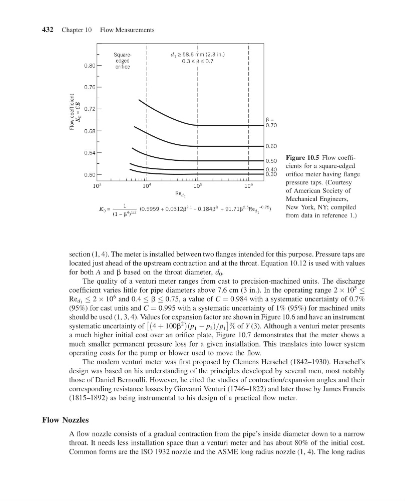
Figure 10.5 Flow coefficients for a square-edged
orifice meter having flange
pressure taps. (Courtesy
of American Society of
Mechanical Engineers,
New York, NY; compiled
from data in reference 1.)
432 Chapter 10 Flow Measurements
13:4:37 Page 432
section (1, 4). The meter is installed between two flanges intended for this purpose. Pressure taps are
located just ahead of the upstream contraction and at the throat. Equation 10.12 is used with values
for both A and b based on the throat diameter, d 0 .
The quality of a venturi meter ranges from cast to precision-machined units. The discharge
coefficient varies little for pipe diameters above 7.6 cm (3 in.). In the operating range 2 Â 10
5
Re d 1 2 Â 10
6 and 0:4 b 0:75, a value of C ¼ 0:984 with a systematic uncertainty of 0.7%
(95%) for cast units and C ¼ 0:995 with a systematic uncertainty of 1% (95%) for machined units
should be used (1, 3, 4). Values for expansion factor are shown in Figure 10.6 and have an instrument
systematic uncertainty of 4 þ 100b
2
À
Á p 1 À p 2
ð
Þ =p 1
Â
à % of Y (3). Although a venturi meter presents
a much higher initial cost over an orifice plate, Figure 10.7 demonstrates that the meter shows a
much smaller permanent pressure loss for a given installation. This translates into lower system
operating costs for the pump or blower used to move the flow.
The modern venturi meter was first proposed by Clemens Herschel (1842–1930). Herschel’s
design was based on his understanding of the principles developed by several men, most notably
those of Daniel Bernoulli. However, he cited the studies of contraction/expansion angles and their
corresponding resistance losses by Giovanni Venturi (1746–1822) and later those by James Francis
(1815–1892) as being instrumental to his design of a practical flow meter.
Flow Nozzles
A flow nozzle consists of a gradual contraction from the pipe’s inside diameter down to a narrow
throat. It needs less installation space than a venturi meter and has about 80% of the initial cost.
Common forms are the ISO 1932 nozzle and the ASME long radius nozzle (1, 4). The long radius
10
3
10
4
10
5
10
6
Re d 1
K 0 =
1
(0.5959 + 0.0312
2.1 – 0.184
8 + 91.71
2.5
Re d 1
–0.75 )
(1 –
4 )
1/2
Flow coefficient
K
0 =
CE
0.60
0.30
0.40
0.50
0.60
=
0.70
0.64
0.68
0.72
0.76
Squareedged
orifice
0.80
d 1 ≥ 58.6 mm (2.3 in.)
0.3 ≤ ≤ 0.7
Figure 10.5 Flow coefficients for a square-edged
orifice meter having flange
pressure taps. (Courtesy
of American Society of
Mechanical Engineers,
New York, NY; compiled
from data in reference 1.)
432 Chapter 10 Flow Measurements