

E1C10 09/14/2010
13:4:37 Page 431
it introduces a large permanent pressure loss, Dp
ð Þ loss ¼ rgh L , into the flow system. The pressure
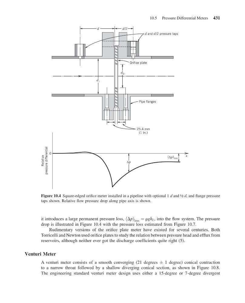
drop is illustrated in Figure 10.4 with the pressure loss estimated from Figure 10.7.
Rudimentary versions of the orifice plate meter have existed for several centuries. Both
Torricelli and Newton used orifice plates to study the relation between pressure head and efflux from
reservoirs, although neither ever got the discharge coefficients quite right (5).
Venturi Meter
A venturi meter consists of a smooth converging (21 degrees Æ 1 degree) conical contraction
to a narrow throat followed by a shallow diverging conical section, as shown in Figure 10.8.
The engineering standard venturi meter design uses either a 15-degree or 7-degree divergent
x
d and d/2 pressure taps
Orifice plate
Pipe flanges
25.4 mm
(1 in.)
0
Relative
pressure differential
d
d/2
Δp
(Δp) loss
d 1
d 0
Figure 10.4 Square-edged orifice meter installed in a pipeline with optional 1 d and ½ d, and flange pressure
taps shown. Relative flow pressure drop along pipe axis is shown.
10.5 Pressure Differential Meters 431
13:4:37 Page 431
it introduces a large permanent pressure loss, Dp
ð Þ loss ¼ rgh L , into the flow system. The pressure
drop is illustrated in Figure 10.4 with the pressure loss estimated from Figure 10.7.
Rudimentary versions of the orifice plate meter have existed for several centuries. Both
Torricelli and Newton used orifice plates to study the relation between pressure head and efflux from
reservoirs, although neither ever got the discharge coefficients quite right (5).
Venturi Meter
A venturi meter consists of a smooth converging (21 degrees Æ 1 degree) conical contraction
to a narrow throat followed by a shallow diverging conical section, as shown in Figure 10.8.
The engineering standard venturi meter design uses either a 15-degree or 7-degree divergent
x
d and d/2 pressure taps
Orifice plate
Pipe flanges
25.4 mm
(1 in.)
0
Relative
pressure differential
d
d/2
Δp
(Δp) loss
d 1
d 0
Figure 10.4 Square-edged orifice meter installed in a pipeline with optional 1 d and ½ d, and flange pressure
taps shown. Relative flow pressure drop along pipe axis is shown.
10.5 Pressure Differential Meters 431