

E1C10 09/14/2010
13:4:37 Page 433
nozzle contraction is that of the quadrant of an ellipse, with the major axis aligned with the flow axis,
as shown in Figure 10.9. The nozzle is typically installed inline, but can also be used at the inlet to
and the outlet from a plenum or reservoir or at the outlet of a pipe. Pressure taps are usually located
(1) at one pipe diameter upstream of the nozzle inlet and at the nozzle throat using either wall or
throat taps, or (2) d and d/2 wall taps located one pipe diameter upstream and one-half diameter
downstream of the upstream nozzle face. The flow rate is determined from Equation 10.12 with
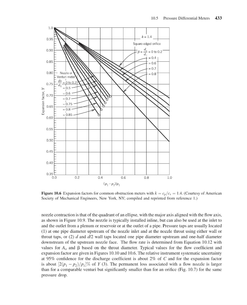
values for A o and b based on the throat diameter. Typical values for the flow coefficient and
expansion factor are given in Figures 10.10 and 10.6. The relative instrument systematic uncertainty
at 95% confidence for the discharge coefficient is about 2% of C and for the expansion factor
is about ½2ðp 1 À p 2 Þ=p 1 % of Y (3). The permanent loss associated with a flow nozzle is larger
than for a comparable venturi but significantly smaller than for an orifice (Fig. 10.7) for the same
pressure drop.
1.0
0.95
0.90
0.85
0.80
0.75
0.70
0.65
0.60
0.55
0.50
0.45
0.40
0.35
0.0
0.2
0.6
0.4
0.8
1.0
Expansion factor,
Y
( p 1 – p 2 )/p 1
= 0.6
= 0.7
= 0.8
k = 1.4
Square-edged orifice
Nozzle or
Venturi meter
do
d 1
= 0 to 0.2
= 0.75
= 0.85
= 0.5
= 0.7
= 0.8
= 0.6
d o
d 1
= 0 to 0.2
=
β
= 0.4
Figure 10.6 Expansion factors for common obstruction meters with k ¼ c p =c v ¼ 1:4. (Courtesy of American
Society of Mechanical Engineers, New York, NY; compiled and reprinted from reference 1.)
10.5 Pressure Differential Meters 433
13:4:37 Page 433
nozzle contraction is that of the quadrant of an ellipse, with the major axis aligned with the flow axis,
as shown in Figure 10.9. The nozzle is typically installed inline, but can also be used at the inlet to
and the outlet from a plenum or reservoir or at the outlet of a pipe. Pressure taps are usually located
(1) at one pipe diameter upstream of the nozzle inlet and at the nozzle throat using either wall or
throat taps, or (2) d and d/2 wall taps located one pipe diameter upstream and one-half diameter
downstream of the upstream nozzle face. The flow rate is determined from Equation 10.12 with
values for A o and b based on the throat diameter. Typical values for the flow coefficient and
expansion factor are given in Figures 10.10 and 10.6. The relative instrument systematic uncertainty
at 95% confidence for the discharge coefficient is about 2% of C and for the expansion factor
is about ½2ðp 1 À p 2 Þ=p 1 % of Y (3). The permanent loss associated with a flow nozzle is larger
than for a comparable venturi but significantly smaller than for an orifice (Fig. 10.7) for the same
pressure drop.
1.0
0.95
0.90
0.85
0.80
0.75
0.70
0.65
0.60
0.55
0.50
0.45
0.40
0.35
0.0
0.2
0.6
0.4
0.8
1.0
Expansion factor,
Y
( p 1 – p 2 )/p 1
= 0.6
= 0.7
= 0.8
k = 1.4
Square-edged orifice
Nozzle or
Venturi meter
do
d 1
= 0 to 0.2
= 0.75
= 0.85
= 0.5
= 0.7
= 0.8
= 0.6
d o
d 1
= 0 to 0.2
=
β
= 0.4
Figure 10.6 Expansion factors for common obstruction meters with k ¼ c p =c v ¼ 1:4. (Courtesy of American
Society of Mechanical Engineers, New York, NY; compiled and reprinted from reference 1.)
10.5 Pressure Differential Meters 433