

E1C09 09/14/2010
15:4:56 Page 413
FIND U
SOLUTION Using Equation 9.51,
U ¼
l
2 sin u=2
f D ¼
632:8 Â 10
À9 m
2 sin 11
=2
ð
Þ
1:41 Â 10
6 Hz
À
Á ¼ 4:655 m=s
Particle Image Velocimetry
Particle image velocimetry (PIV) measures the full-field instantaneous velocities in a planar cross
section of a flow. The technique tracks the time displacement of particles, which are assumed to
follow the flow. Principle components for the technique are a coherent light source (laser beam),
optics, a CCD-camera, and dedicated signal interrogation software.
In a simple overview, the image of particles suspended in the flow are illuminated and recorded
during very-short-duration repetitive flashes of a laser beam. These images are recorded and
compared. The distance traveled by any particle during the period between flashes is a measure of its
velocity. By repeatedly flashing the laser, in the manner of a strobe light, the particle positions can be
tracked and velocity as a function of time obtained.
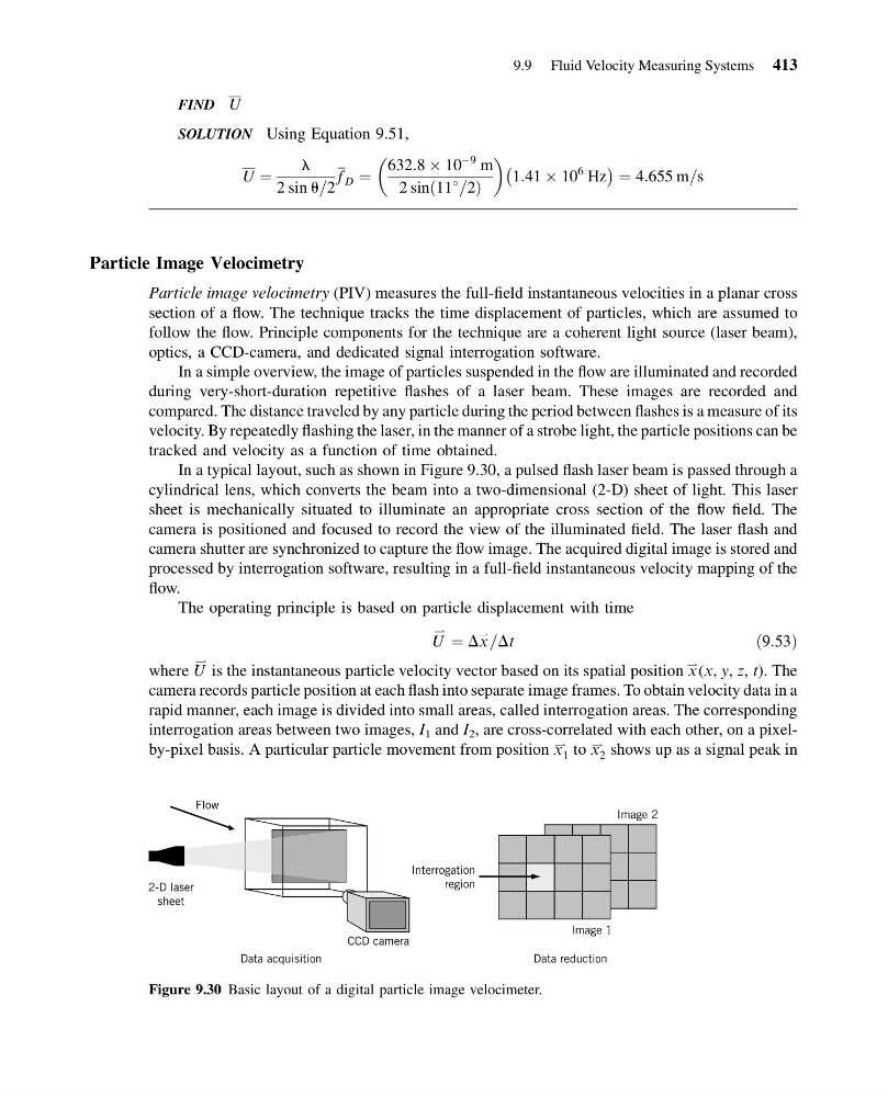
In a typical layout, such as shown in Figure 9.30, a pulsed flash laser beam is passed through a
cylindrical lens, which converts the beam into a two-dimensional (2-D) sheet of light. This laser
sheet is mechanically situated to illuminate an appropriate cross section of the flow field. The
camera is positioned and focused to record the view of the illuminated field. The laser flash and
camera shutter are synchronized to capture the flow image. The acquired digital image is stored and
processed by interrogation software, resulting in a full-field instantaneous velocity mapping of the
flow.
The operating principle is based on particle displacement with time
U
* ¼ Dx
* =Dt
ð9:53Þ
where U
* is the instantaneous particle velocity vector based on its spatial position x
* (x, y, z, t). The
camera records particle position at each flash into separate image frames. To obtain velocity data in a
rapid manner, each image is divided into small areas, called interrogation areas. The corresponding
interrogation areas between two images, I 1 and I 2 , are cross-correlated with each other, on a pixelby-pixel basis. A particular particle movement from position x
*
1 to x
*
2 shows up as a signal peak in
Figure 9.30 Basic layout of a digital particle image velocimeter.
9.9 Fluid Velocity Measuring Systems 413
15:4:56 Page 413
FIND U
SOLUTION Using Equation 9.51,
U ¼
l
2 sin u=2
f D ¼
632:8 Â 10
À9 m
2 sin 11
=2
ð
Þ
1:41 Â 10
6 Hz
À
Á ¼ 4:655 m=s
Particle Image Velocimetry
Particle image velocimetry (PIV) measures the full-field instantaneous velocities in a planar cross
section of a flow. The technique tracks the time displacement of particles, which are assumed to
follow the flow. Principle components for the technique are a coherent light source (laser beam),
optics, a CCD-camera, and dedicated signal interrogation software.
In a simple overview, the image of particles suspended in the flow are illuminated and recorded
during very-short-duration repetitive flashes of a laser beam. These images are recorded and
compared. The distance traveled by any particle during the period between flashes is a measure of its
velocity. By repeatedly flashing the laser, in the manner of a strobe light, the particle positions can be
tracked and velocity as a function of time obtained.
In a typical layout, such as shown in Figure 9.30, a pulsed flash laser beam is passed through a
cylindrical lens, which converts the beam into a two-dimensional (2-D) sheet of light. This laser
sheet is mechanically situated to illuminate an appropriate cross section of the flow field. The
camera is positioned and focused to record the view of the illuminated field. The laser flash and
camera shutter are synchronized to capture the flow image. The acquired digital image is stored and
processed by interrogation software, resulting in a full-field instantaneous velocity mapping of the
flow.
The operating principle is based on particle displacement with time
U
* ¼ Dx
* =Dt
ð9:53Þ
where U
* is the instantaneous particle velocity vector based on its spatial position x
* (x, y, z, t). The
camera records particle position at each flash into separate image frames. To obtain velocity data in a
rapid manner, each image is divided into small areas, called interrogation areas. The corresponding
interrogation areas between two images, I 1 and I 2 , are cross-correlated with each other, on a pixelby-pixel basis. A particular particle movement from position x
*
1 to x
*
2 shows up as a signal peak in
Figure 9.30 Basic layout of a digital particle image velocimeter.
9.9 Fluid Velocity Measuring Systems 413