

E1C09 09/14/2010
15:4:56 Page 411
where f i is the frequency of the incident laser beam and f D is the Doppler shift frequency. Using
visible light, an incident laser beam frequency is on the order of 10
14 Hz. For most engineering
applications, the velocities are such that the Doppler shift frequency, f D , is on the order of 10
3 to 10
7
Hz. Such a small shift in the incident frequency can be difficult to detect in a practical instrument.
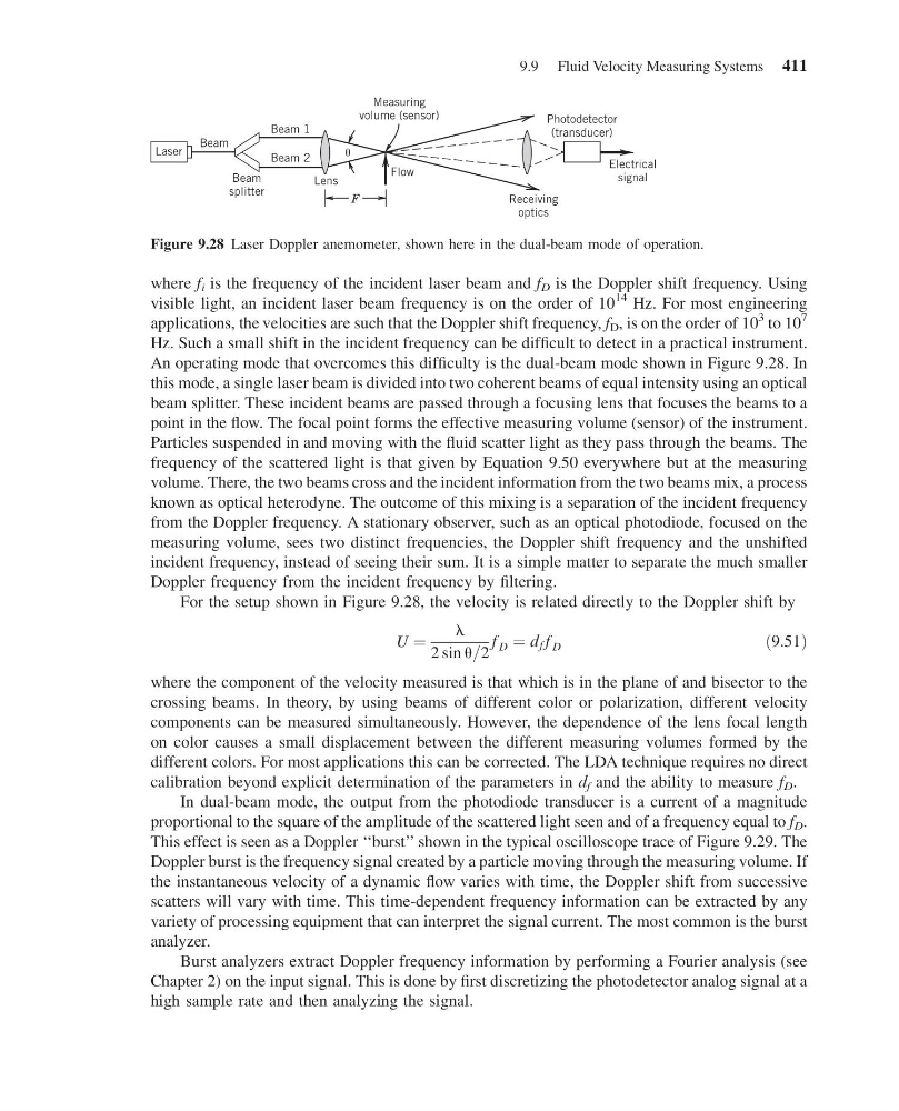
An operating mode that overcomes this difficulty is the dual-beam mode shown in Figure 9.28. In
this mode, a single laser beam is divided into two coherent beams of equal intensity using an optical
beam splitter. These incident beams are passed through a focusing lens that focuses the beams to a
point in the flow. The focal point forms the effective measuring volume (sensor) of the instrument.
Particles suspended in and moving with the fluid scatter light as they pass through the beams. The
frequency of the scattered light is that given by Equation 9.50 everywhere but at the measuring
volume. There, the two beams cross and the incident information from the two beams mix, a process
known as optical heterodyne. The outcome of this mixing is a separation of the incident frequency
from the Doppler frequency. A stationary observer, such as an optical photodiode, focused on the
measuring volume, sees two distinct frequencies, the Doppler shift frequency and the unshifted
incident frequency, instead of seeing their sum. It is a simple matter to separate the much smaller
Doppler frequency from the incident frequency by filtering.
For the setup shown in Figure 9.28, the velocity is related directly to the Doppler shift by
U ¼
l
2 sin u=2
f D ¼ d f f D
ð9:51Þ
where the component of the velocity measured is that which is in the plane of and bisector to the
crossing beams. In theory, by using beams of different color or polarization, different velocity
components can be measured simultaneously. However, the dependence of the lens focal length
on color causes a small displacement between the different measuring volumes formed by the
different colors. For most applications this can be corrected. The LDA technique requires no direct
calibration beyond explicit determination of the parameters in d f and the ability to measure f D .
In dual-beam mode, the output from the photodiode transducer is a current of a magnitude
proportional to the square of the amplitude of the scattered light seen and of a frequency equal to f D .
This effect is seen as a Doppler ‘‘burst’’ shown in the typical oscilloscope trace of Figure 9.29. The
Doppler burst is the frequency signal created by a particle moving through the measuring volume. If
the instantaneous velocity of a dynamic flow varies with time, the Doppler shift from successive
scatters will vary with time. This time-dependent frequency information can be extracted by any
variety of processing equipment that can interpret the signal current. The most common is the burst
analyzer.
Burst analyzers extract Doppler frequency information by performing a Fourier analysis (see
Chapter 2) on the input signal. This is done by first discretizing the photodetector analog signal at a
high sample rate and then analyzing the signal.
Beam 1
Beam
splitter
Beam
Beam 2
Lens
Flow
Measuring
volume (sensor)
Electrical
signal
Receiving
optics
Photodetector
(transducer)
F
Laser
Figure 9.28 Laser Doppler anemometer, shown here in the dual-beam mode of operation.
9.9 Fluid Velocity Measuring Systems 411
15:4:56 Page 411
where f i is the frequency of the incident laser beam and f D is the Doppler shift frequency. Using
visible light, an incident laser beam frequency is on the order of 10
14 Hz. For most engineering
applications, the velocities are such that the Doppler shift frequency, f D , is on the order of 10
3 to 10
7
Hz. Such a small shift in the incident frequency can be difficult to detect in a practical instrument.
An operating mode that overcomes this difficulty is the dual-beam mode shown in Figure 9.28. In
this mode, a single laser beam is divided into two coherent beams of equal intensity using an optical
beam splitter. These incident beams are passed through a focusing lens that focuses the beams to a
point in the flow. The focal point forms the effective measuring volume (sensor) of the instrument.
Particles suspended in and moving with the fluid scatter light as they pass through the beams. The
frequency of the scattered light is that given by Equation 9.50 everywhere but at the measuring
volume. There, the two beams cross and the incident information from the two beams mix, a process
known as optical heterodyne. The outcome of this mixing is a separation of the incident frequency
from the Doppler frequency. A stationary observer, such as an optical photodiode, focused on the
measuring volume, sees two distinct frequencies, the Doppler shift frequency and the unshifted
incident frequency, instead of seeing their sum. It is a simple matter to separate the much smaller
Doppler frequency from the incident frequency by filtering.
For the setup shown in Figure 9.28, the velocity is related directly to the Doppler shift by
U ¼
l
2 sin u=2
f D ¼ d f f D
ð9:51Þ
where the component of the velocity measured is that which is in the plane of and bisector to the
crossing beams. In theory, by using beams of different color or polarization, different velocity
components can be measured simultaneously. However, the dependence of the lens focal length
on color causes a small displacement between the different measuring volumes formed by the
different colors. For most applications this can be corrected. The LDA technique requires no direct
calibration beyond explicit determination of the parameters in d f and the ability to measure f D .
In dual-beam mode, the output from the photodiode transducer is a current of a magnitude
proportional to the square of the amplitude of the scattered light seen and of a frequency equal to f D .
This effect is seen as a Doppler ‘‘burst’’ shown in the typical oscilloscope trace of Figure 9.29. The
Doppler burst is the frequency signal created by a particle moving through the measuring volume. If
the instantaneous velocity of a dynamic flow varies with time, the Doppler shift from successive
scatters will vary with time. This time-dependent frequency information can be extracted by any
variety of processing equipment that can interpret the signal current. The most common is the burst
analyzer.
Burst analyzers extract Doppler frequency information by performing a Fourier analysis (see
Chapter 2) on the input signal. This is done by first discretizing the photodetector analog signal at a
high sample rate and then analyzing the signal.
Beam 1
Beam
splitter
Beam
Beam 2
Lens
Flow
Measuring
volume (sensor)
Electrical
signal
Receiving
optics
Photodetector
(transducer)
F
Laser
Figure 9.28 Laser Doppler anemometer, shown here in the dual-beam mode of operation.
9.9 Fluid Velocity Measuring Systems 411