

E1C09 09/14/2010
15:4:55 Page 403
The total system compliance could be measured using Equation 9.20 by closing the pressure
tap, increasing the fluid volume in the tubing by a small known amount, such as by syringe, and
measuring the corresponding pressure change.
Liquids
Liquids are relatively incompressible, so that the compression-restoring force in the transmission
line is due primarily to the compliance in the transducer, which is a transducer specification, for use
in Equations 9.24 and 9.25. Connecting tubing can usually be considered rigid for the underlying
assumptions of the above lumped parameter analysis. Thick-walled, flexible tubing is often used,
but this is fairly rigid and its compliance can be ignored. If need be, the compliance can be measured.
Gases
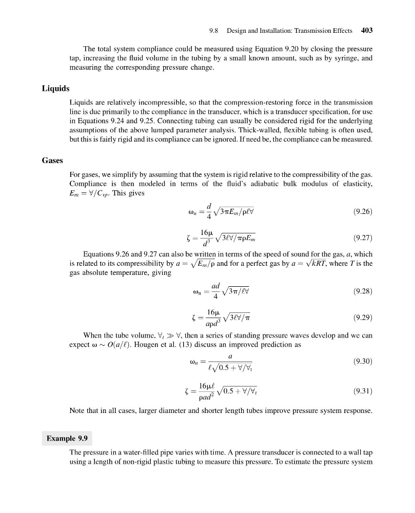
For gases, we simplify by assuming that the system is rigid relative to the compressibility of the gas.
Compliance is then modeled in terms of the fluid’s adiabatic bulk modulus of elasticity,
E m ¼ 8=C vp . This gives
v n ¼
d
4
ffiffiffiffiffiffiffiffiffiffiffiffiffiffiffiffiffiffiffiffiffi
3pE m =r‘8
p
ð9:26Þ
z ¼
16m
d
3
ffiffiffiffiffiffiffiffiffiffiffiffiffiffiffiffiffiffiffiffiffi
3‘8=prE m
p
ð9:27Þ
Equations 9.26 and 9.27 can also be written in terms of the speed of sound for the gas, a, which
is related to its compressibility by a ¼
ffiffiffiffiffiffiffiffiffiffiffi
E m =r
p
and for a perfect gas by a ¼
ffiffiffiffiffiffiffiffiffi
kRT
p
, where T is the
gas absolute temperature, giving
v n ¼
ad
4
ffiffiffiffiffiffiffiffiffiffiffiffiffi
3p=‘8
p
ð9:28Þ
z ¼
16m
ard
3
ffiffiffiffiffiffiffiffiffiffiffiffiffi
3‘8=p
p
ð9:29Þ
When the tube volume, 8 t ) 8, then a series of standing pressure waves develop and we can
expect v $ O a=‘
ð Þ. Hougen et al. (13) discuss an improved prediction as
v n ¼
a
‘
ffiffiffiffiffiffiffiffiffiffiffiffiffiffiffiffiffiffiffiffiffi
0:5 þ 8=8 t
p
ð9:30Þ
z ¼
16m‘
rad
2
ffiffiffiffiffiffiffiffiffiffiffiffiffiffiffiffiffiffiffiffiffi
0:5 þ 8=8 t
p
ð9:31Þ
Note that in all cases, larger diameter and shorter length tubes improve pressure system response.
Example 9.9
The pressure in a water-filled pipe varies with time. A pressure transducer is connected to a wall tap
using a length of non-rigid plastic tubing to measure this pressure. To estimate the pressure system
9.8 Design and Installation: Transmission Effects 403
15:4:55 Page 403
The total system compliance could be measured using Equation 9.20 by closing the pressure
tap, increasing the fluid volume in the tubing by a small known amount, such as by syringe, and
measuring the corresponding pressure change.
Liquids
Liquids are relatively incompressible, so that the compression-restoring force in the transmission
line is due primarily to the compliance in the transducer, which is a transducer specification, for use
in Equations 9.24 and 9.25. Connecting tubing can usually be considered rigid for the underlying
assumptions of the above lumped parameter analysis. Thick-walled, flexible tubing is often used,
but this is fairly rigid and its compliance can be ignored. If need be, the compliance can be measured.
Gases
For gases, we simplify by assuming that the system is rigid relative to the compressibility of the gas.
Compliance is then modeled in terms of the fluid’s adiabatic bulk modulus of elasticity,
E m ¼ 8=C vp . This gives
v n ¼
d
4
ffiffiffiffiffiffiffiffiffiffiffiffiffiffiffiffiffiffiffiffiffi
3pE m =r‘8
p
ð9:26Þ
z ¼
16m
d
3
ffiffiffiffiffiffiffiffiffiffiffiffiffiffiffiffiffiffiffiffiffi
3‘8=prE m
p
ð9:27Þ
Equations 9.26 and 9.27 can also be written in terms of the speed of sound for the gas, a, which
is related to its compressibility by a ¼
ffiffiffiffiffiffiffiffiffiffiffi
E m =r
p
and for a perfect gas by a ¼
ffiffiffiffiffiffiffiffiffi
kRT
p
, where T is the
gas absolute temperature, giving
v n ¼
ad
4
ffiffiffiffiffiffiffiffiffiffiffiffiffi
3p=‘8
p
ð9:28Þ
z ¼
16m
ard
3
ffiffiffiffiffiffiffiffiffiffiffiffiffi
3‘8=p
p
ð9:29Þ
When the tube volume, 8 t ) 8, then a series of standing pressure waves develop and we can
expect v $ O a=‘
ð Þ. Hougen et al. (13) discuss an improved prediction as
v n ¼
a
‘
ffiffiffiffiffiffiffiffiffiffiffiffiffiffiffiffiffiffiffiffiffi
0:5 þ 8=8 t
p
ð9:30Þ
z ¼
16m‘
rad
2
ffiffiffiffiffiffiffiffiffiffiffiffiffiffiffiffiffiffiffiffiffi
0:5 þ 8=8 t
p
ð9:31Þ
Note that in all cases, larger diameter and shorter length tubes improve pressure system response.
Example 9.9
The pressure in a water-filled pipe varies with time. A pressure transducer is connected to a wall tap
using a length of non-rigid plastic tubing to measure this pressure. To estimate the pressure system
9.8 Design and Installation: Transmission Effects 403