

E1C09 09/14/2010
15:4:54 Page 398
Static Pressure Measurement
The local value of static pressure in a moving stream is measured by sensing the pressure in the
direction that is normal to the flow streamline. Within ducted flows, static pressure is sensed by wall
taps, which are small, burr-free, holes drilled into the duct wall perpendicular to the flow direction at
the measurement point. The tap is fitted with a hose or tube, which is connected to a pressure gauge
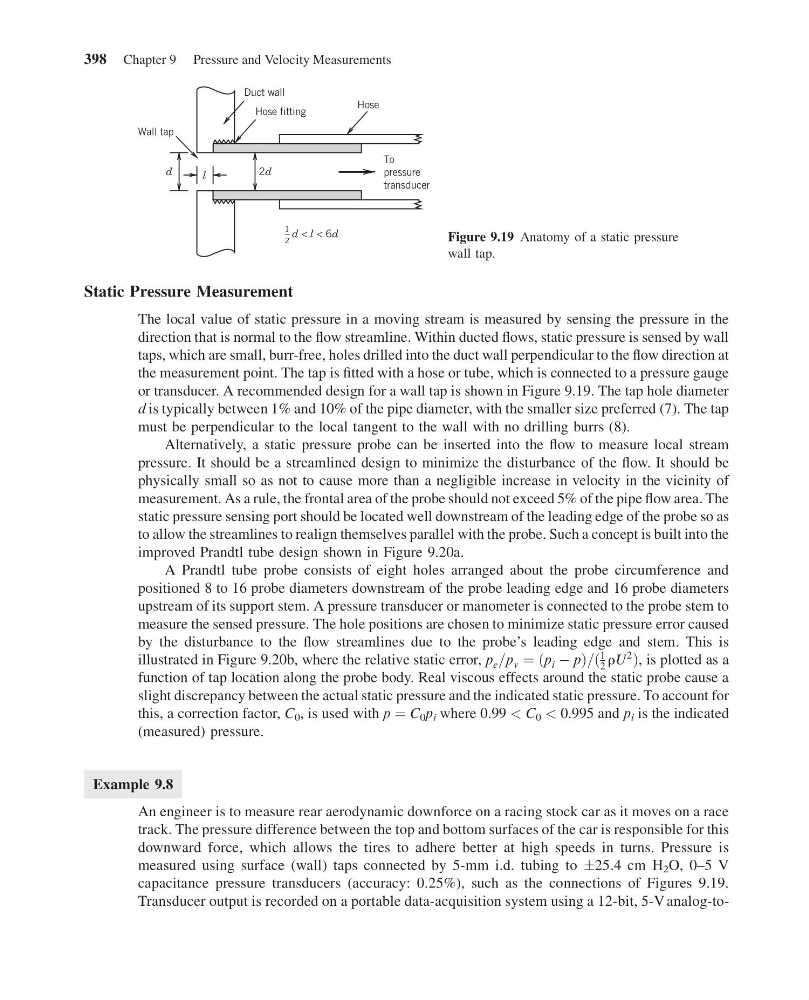
or transducer. A recommended design for a wall tap is shown in Figure 9.19. The tap hole diameter
d is typically between 1% and 10% of the pipe diameter, with the smaller size preferred (7). The tap
must be perpendicular to the local tangent to the wall with no drilling burrs (8).
Alternatively, a static pressure probe can be inserted into the flow to measure local stream
pressure. It should be a streamlined design to minimize the disturbance of the flow. It should be
physically small so as not to cause more than a negligible increase in velocity in the vicinity of
measurement. As a rule, the frontal area of the probe should not exceed 5% of the pipe flow area. The
static pressure sensing port should be located well downstream of the leading edge of the probe so as
to allow the streamlines to realign themselves parallel with the probe. Such a concept is built into the
improved Prandtl tube design shown in Figure 9.20a.
A Prandtl tube probe consists of eight holes arranged about the probe circumference and
positioned 8 to 16 probe diameters downstream of the probe leading edge and 16 probe diameters
upstream of its support stem. A pressure transducer or manometer is connected to the probe stem to
measure the sensed pressure. The hole positions are chosen to minimize static pressure error caused
by the disturbance to the flow streamlines due to the probe’s leading edge and stem. This is
illustrated in Figure 9.20b, where the relative static error, p e =p v ¼ ðp i À pÞ=ð
1
2 rU
2
Þ, is plotted as a
function of tap location along the probe body. Real viscous effects around the static probe cause a
slight discrepancy between the actual static pressure and the indicated static pressure. To account for
this, a correction factor, C 0 , is used with p ¼ C 0 p i where 0.99 < C 0 < 0.995 and p i is the indicated
(measured) pressure.
Example 9.8
An engineer is to measure rear aerodynamic downforce on a racing stock car as it moves on a race
track. The pressure difference between the top and bottom surfaces of the car is responsible for this
downward force, which allows the tires to adhere better at high speeds in turns. Pressure is
measured using surface (wall) taps connected by 5-mm i.d. tubing to Æ25.4 cm H 2 O, 0–5 V
capacitance pressure transducers (accuracy: 0.25%), such as the connections of Figures 9.19.
Transducer output is recorded on a portable data-acquisition system using a 12-bit, 5-V analog-toWall tap
d
l
2d
Duct wall
Hose fitting
Hose
To
pressure
transducer
1
2
d < l < 6d
Figure 9.19 Anatomy of a static pressure
wall tap.
398 Chapter 9 Pressure and Velocity Measurements
15:4:54 Page 398
Static Pressure Measurement
The local value of static pressure in a moving stream is measured by sensing the pressure in the
direction that is normal to the flow streamline. Within ducted flows, static pressure is sensed by wall
taps, which are small, burr-free, holes drilled into the duct wall perpendicular to the flow direction at
the measurement point. The tap is fitted with a hose or tube, which is connected to a pressure gauge
or transducer. A recommended design for a wall tap is shown in Figure 9.19. The tap hole diameter
d is typically between 1% and 10% of the pipe diameter, with the smaller size preferred (7). The tap
must be perpendicular to the local tangent to the wall with no drilling burrs (8).
Alternatively, a static pressure probe can be inserted into the flow to measure local stream
pressure. It should be a streamlined design to minimize the disturbance of the flow. It should be
physically small so as not to cause more than a negligible increase in velocity in the vicinity of
measurement. As a rule, the frontal area of the probe should not exceed 5% of the pipe flow area. The
static pressure sensing port should be located well downstream of the leading edge of the probe so as
to allow the streamlines to realign themselves parallel with the probe. Such a concept is built into the
improved Prandtl tube design shown in Figure 9.20a.
A Prandtl tube probe consists of eight holes arranged about the probe circumference and
positioned 8 to 16 probe diameters downstream of the probe leading edge and 16 probe diameters
upstream of its support stem. A pressure transducer or manometer is connected to the probe stem to
measure the sensed pressure. The hole positions are chosen to minimize static pressure error caused
by the disturbance to the flow streamlines due to the probe’s leading edge and stem. This is
illustrated in Figure 9.20b, where the relative static error, p e =p v ¼ ðp i À pÞ=ð
1
2 rU
2
Þ, is plotted as a
function of tap location along the probe body. Real viscous effects around the static probe cause a
slight discrepancy between the actual static pressure and the indicated static pressure. To account for
this, a correction factor, C 0 , is used with p ¼ C 0 p i where 0.99 < C 0 < 0.995 and p i is the indicated
(measured) pressure.
Example 9.8
An engineer is to measure rear aerodynamic downforce on a racing stock car as it moves on a race
track. The pressure difference between the top and bottom surfaces of the car is responsible for this
downward force, which allows the tires to adhere better at high speeds in turns. Pressure is
measured using surface (wall) taps connected by 5-mm i.d. tubing to Æ25.4 cm H 2 O, 0–5 V
capacitance pressure transducers (accuracy: 0.25%), such as the connections of Figures 9.19.
Transducer output is recorded on a portable data-acquisition system using a 12-bit, 5-V analog-toWall tap
d
l
2d
Duct wall
Hose fitting
Hose
To
pressure
transducer
1
2
d < l < 6d
Figure 9.19 Anatomy of a static pressure
wall tap.
398 Chapter 9 Pressure and Velocity Measurements