

E1C09 09/14/2010
15:4:54 Page 397
However, because point 2 is the stagnation point, U 2 ¼ 0, and
p 2 ¼ p t ¼ p 1 þ rU
2
1 =2
ð9:17Þ
Hence, it follows that p 2 > p 1 by an amount equal to p v ¼ rU
2
1 =2, called the dynamic pressure, an
amount equivalent to the kinetic energy per unit mass of the flow as it moves along the streamline. If
no energy is lost through irreversible processes, such as through a transfer of heat,
1 this translational
kinetic energy is transferred completely into p 2 . The value of p 2 is known as the stagnation or the
total pressure and is noted as p t . The total pressure can be determined by bringing the flow to rest at
a point in an isentropic manner.
The pressures at 1, 3, and 4 are known as static pressures
2 of the flow. The static pressure is that
pressure sensed by a fluid particle as it moves with the same velocity as the local flow. The static pressure
and velocity at points 1 and 3 are given the special names of the ‘‘freestream static pressure’’ and
‘‘freestream velocity.’’ Since U 4 > U 3 , Equation 9.16 shows that p 4 that the total pressure is the sum of the static and dynamic pressures anywhere in the flow.
Total Pressure Measurement
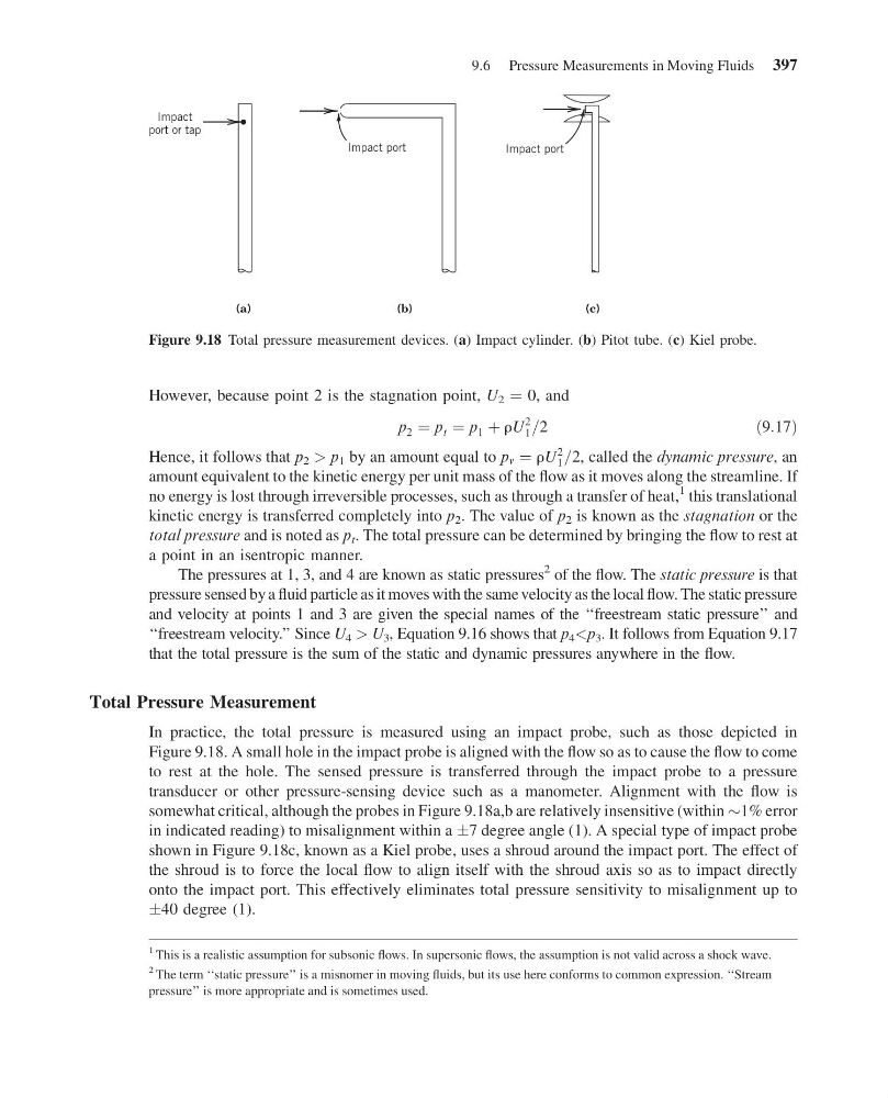
In practice, the total pressure is measured using an impact probe, such as those depicted in
Figure 9.18. A small hole in the impact probe is aligned with the flow so as to cause the flow to come
to rest at the hole. The sensed pressure is transferred through the impact probe to a pressure
transducer or other pressure-sensing device such as a manometer. Alignment with the flow is
somewhat critical, although the probes in Figure 9.18a,b are relatively insensitive (within $1% error
in indicated reading) to misalignment within a Æ7 degree angle (1). A special type of impact probe
shown in Figure 9.18c, known as a Kiel probe, uses a shroud around the impact port. The effect of
the shroud is to force the local flow to align itself with the shroud axis so as to impact directly
onto the impact port. This effectively eliminates total pressure sensitivity to misalignment up to
Æ40 degree (1).
1 This is a realistic assumption for subsonic flows. In supersonic flows, the assumption is not valid across a shock wave.
2 The term ‘‘static pressure’’ is a misnomer in moving fluids, but its use here conforms to common expression. ‘‘Stream
pressure’’ is more appropriate and is sometimes used.
Impact port
(c)
(a)
Impact
port or tap
Impact port
(b)
Figure 9.18 Total pressure measurement devices. (a) Impact cylinder. (b) Pitot tube. (c) Kiel probe.
9.6 Pressure Measurements in Moving Fluids 397
15:4:54 Page 397
However, because point 2 is the stagnation point, U 2 ¼ 0, and
p 2 ¼ p t ¼ p 1 þ rU
2
1 =2
ð9:17Þ
Hence, it follows that p 2 > p 1 by an amount equal to p v ¼ rU
2
1 =2, called the dynamic pressure, an
amount equivalent to the kinetic energy per unit mass of the flow as it moves along the streamline. If
no energy is lost through irreversible processes, such as through a transfer of heat,
1 this translational
kinetic energy is transferred completely into p 2 . The value of p 2 is known as the stagnation or the
total pressure and is noted as p t . The total pressure can be determined by bringing the flow to rest at
a point in an isentropic manner.
The pressures at 1, 3, and 4 are known as static pressures
2 of the flow. The static pressure is that
pressure sensed by a fluid particle as it moves with the same velocity as the local flow. The static pressure
and velocity at points 1 and 3 are given the special names of the ‘‘freestream static pressure’’ and
‘‘freestream velocity.’’ Since U 4 > U 3 , Equation 9.16 shows that p 4 that the total pressure is the sum of the static and dynamic pressures anywhere in the flow.
Total Pressure Measurement
In practice, the total pressure is measured using an impact probe, such as those depicted in
Figure 9.18. A small hole in the impact probe is aligned with the flow so as to cause the flow to come
to rest at the hole. The sensed pressure is transferred through the impact probe to a pressure
transducer or other pressure-sensing device such as a manometer. Alignment with the flow is
somewhat critical, although the probes in Figure 9.18a,b are relatively insensitive (within $1% error
in indicated reading) to misalignment within a Æ7 degree angle (1). A special type of impact probe
shown in Figure 9.18c, known as a Kiel probe, uses a shroud around the impact port. The effect of
the shroud is to force the local flow to align itself with the shroud axis so as to impact directly
onto the impact port. This effectively eliminates total pressure sensitivity to misalignment up to
Æ40 degree (1).
1 This is a realistic assumption for subsonic flows. In supersonic flows, the assumption is not valid across a shock wave.
2 The term ‘‘static pressure’’ is a misnomer in moving fluids, but its use here conforms to common expression. ‘‘Stream
pressure’’ is more appropriate and is sometimes used.
Impact port
(c)
(a)
Impact
port or tap
Impact port
(b)
Figure 9.18 Total pressure measurement devices. (a) Impact cylinder. (b) Pitot tube. (c) Kiel probe.
9.6 Pressure Measurements in Moving Fluids 397