

E1C08 09/14/2010
14:54:1 Page 357
In our example, the temperature of the thermometer is the thermodynamic equilibrium temperature that results from the radiant energy gained from the sun, convective exchange with the air, and
conduction heat transfer with the surface on which it is resting. Considering the fact that these
thermometers typically have a glass cover that ensures a greenhouse effect, it is very likely that the
thermometer temperature is significantly higher than the air temperature.
The physical mechanisms that may cause a temperature probe to indicate a temperature
different from that intended include conduction, radiation, and velocity recovery errors. In any
real measurement system, their effects could be coupled, and therefore should not be considered
independently. However, for simplicity, we will consider each separately because our purpose is
to provide only estimates of the errors, and not to provide predictive techniques for correcting
measured temperatures. The goal of the measurement engineer should be to minimize these
errors, as far as possible, through the careful installation and design of temperature probes.
Conduction Errors
Errors that result from conduction heat transfer between the measuring environment and the ambient
are often called immersion errors. Consider the temperature probe shown in Figure 8.33. In many
circumstances, a temperature probe extends from the measuring environment through a wall into the
ambient environment, where indicating or recording systems are located. The probe and the
electrical leads form a path for the conduction of energy from the measuring environment to the
ambient. The fundamental nature of the error created by conduction in measured temperatures can
be illustrated by the model of a temperature probe shown in Figure 8.34. The essential physics of
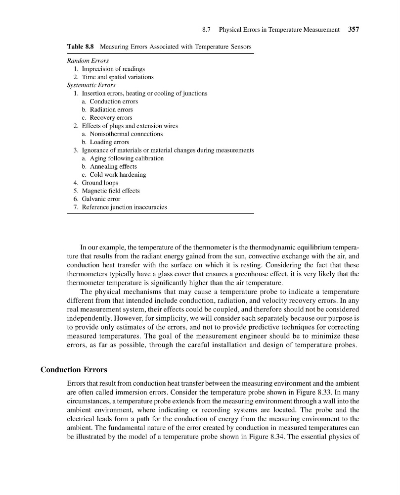
Table 8.8 Measuring Errors Associated with Temperature Sensors
Random Errors
1. Imprecision of readings
2. Time and spatial variations
Systematic Errors
1. Insertion errors, heating or cooling of junctions
a. Conduction errors
b. Radiation errors
c. Recovery errors
2. Effects of plugs and extension wires
a. Nonisothermal connections
b. Loading errors
3. Ignorance of materials or material changes during measurements
a. Aging following calibration
b. Annealing effects
c. Cold work hardening
4. Ground loops
5. Magnetic field effects
6. Galvanic error
7. Reference junction inaccuracies
8.7 Physical Errors in Temperature Measurement 357
14:54:1 Page 357
In our example, the temperature of the thermometer is the thermodynamic equilibrium temperature that results from the radiant energy gained from the sun, convective exchange with the air, and
conduction heat transfer with the surface on which it is resting. Considering the fact that these
thermometers typically have a glass cover that ensures a greenhouse effect, it is very likely that the
thermometer temperature is significantly higher than the air temperature.
The physical mechanisms that may cause a temperature probe to indicate a temperature
different from that intended include conduction, radiation, and velocity recovery errors. In any
real measurement system, their effects could be coupled, and therefore should not be considered
independently. However, for simplicity, we will consider each separately because our purpose is
to provide only estimates of the errors, and not to provide predictive techniques for correcting
measured temperatures. The goal of the measurement engineer should be to minimize these
errors, as far as possible, through the careful installation and design of temperature probes.
Conduction Errors
Errors that result from conduction heat transfer between the measuring environment and the ambient
are often called immersion errors. Consider the temperature probe shown in Figure 8.33. In many
circumstances, a temperature probe extends from the measuring environment through a wall into the
ambient environment, where indicating or recording systems are located. The probe and the
electrical leads form a path for the conduction of energy from the measuring environment to the
ambient. The fundamental nature of the error created by conduction in measured temperatures can
be illustrated by the model of a temperature probe shown in Figure 8.34. The essential physics of
Table 8.8 Measuring Errors Associated with Temperature Sensors
Random Errors
1. Imprecision of readings
2. Time and spatial variations
Systematic Errors
1. Insertion errors, heating or cooling of junctions
a. Conduction errors
b. Radiation errors
c. Recovery errors
2. Effects of plugs and extension wires
a. Nonisothermal connections
b. Loading errors
3. Ignorance of materials or material changes during measurements
a. Aging following calibration
b. Annealing effects
c. Cold work hardening
4. Ground loops
5. Magnetic field effects
6. Galvanic error
7. Reference junction inaccuracies
8.7 Physical Errors in Temperature Measurement 357