

E1C08 09/14/2010
14:54:1 Page 356
thermometer. The operating range of this thermometer is 300
to 1900
C. Signal transmission is
accomplished using standard, low-temperature fiber optics. A specific wavelength band of the
transmitted radiation is detected and measured, and these raw data are reduced to yield the
temperature of the blackbody sensor.
The absence of electrical signals associated with the sensor signal provides excellent immunity
from electromagnetic and radiofrequency interference. The measurement system has superior
frequency response and sensitivity. The system has been employed for measurement in combustion
applications. Temperature resolution of 0.1 mK is possible.
8.7 PHYSICAL ERRORS IN TEMPERATURE MEASUREMENT
In general, errors in temperature measurement derive from two fundamental sources. The first source
of errors derives from uncertain information about the temperature of the sensor itself. Such
uncertainties can result from random interpolation errors, calibration systematic errors, or a host
of other error sources. Instrument and procedural uncertainty in the sensor temperature can be reduced
by improved calibration or by changes in the measuring and recording instruments. However, errors in
temperature measurement can still occur even if the temperature of the sensor was measured exactly.
In such cases, the probe does not sense accurately the temperature it was intended to measure.
A list of typical errors associated with the use of temperature sensors is provided in Table 8.8.
Random errors in temperature measurements are a result of resolution limits of measuring and recording
equipment, time variations in extraneous variables, and other sources of variation. Thermocouples have
some characteristics that can lead to both systematic and random errors, such as the effect of extension
wires and connectors. Another major source of error for thermocouples involves the accuracy of the
reference junction. Ground loops can lead to spurious readings, especially when thermocouple outputs
are amplified for control or data-acquisition purposes. As with any measurement system, calibration of
the entire measurement system, in place if possible, is the best means of identifying error sources and
reducing the resulting measurement uncertainty to acceptable limits.
Insertion Errors
This discussion focuses on ensuring that a sensor output accurately represents the temperature it is
intended to measure. For example, suppose it is desired to measure the outdoor temperature. This
measurement could employ a large dial thermometer, which might be placed on a football field or a
tennis court in the direct sunlight, and assumed to represent ‘‘the temperature,’’ perhaps as high as
50
C (120
F). But what temperature is being indicated by this thermometer? Certainly the
thermometer is not measuring the air temperature, nor is it measuring the temperature of the field
or the court. The thermometer is subject to the very sources of error we wish to describe and analyze.
The thermometer, very simply, indicates its own temperature!
Optical path to
photodetector
1
2
3
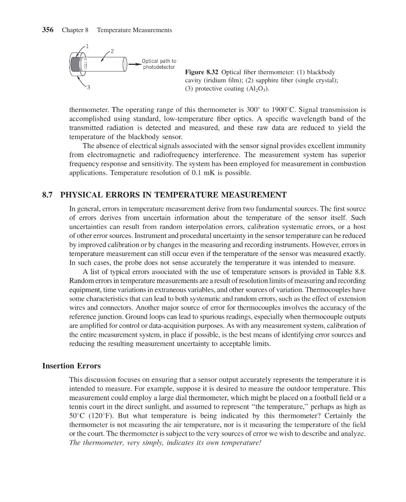
Figure 8.32 Optical fiber thermometer: (1) blackbody
cavity (iridium film); (2) sapphire fiber (single crystal);
(3) protective coating (Al 2 O 3 ).
356 Chapter 8 Temperature Measurements
14:54:1 Page 356
thermometer. The operating range of this thermometer is 300
to 1900
C. Signal transmission is
accomplished using standard, low-temperature fiber optics. A specific wavelength band of the
transmitted radiation is detected and measured, and these raw data are reduced to yield the
temperature of the blackbody sensor.
The absence of electrical signals associated with the sensor signal provides excellent immunity
from electromagnetic and radiofrequency interference. The measurement system has superior
frequency response and sensitivity. The system has been employed for measurement in combustion
applications. Temperature resolution of 0.1 mK is possible.
8.7 PHYSICAL ERRORS IN TEMPERATURE MEASUREMENT
In general, errors in temperature measurement derive from two fundamental sources. The first source
of errors derives from uncertain information about the temperature of the sensor itself. Such
uncertainties can result from random interpolation errors, calibration systematic errors, or a host
of other error sources. Instrument and procedural uncertainty in the sensor temperature can be reduced
by improved calibration or by changes in the measuring and recording instruments. However, errors in
temperature measurement can still occur even if the temperature of the sensor was measured exactly.
In such cases, the probe does not sense accurately the temperature it was intended to measure.
A list of typical errors associated with the use of temperature sensors is provided in Table 8.8.
Random errors in temperature measurements are a result of resolution limits of measuring and recording
equipment, time variations in extraneous variables, and other sources of variation. Thermocouples have
some characteristics that can lead to both systematic and random errors, such as the effect of extension
wires and connectors. Another major source of error for thermocouples involves the accuracy of the
reference junction. Ground loops can lead to spurious readings, especially when thermocouple outputs
are amplified for control or data-acquisition purposes. As with any measurement system, calibration of
the entire measurement system, in place if possible, is the best means of identifying error sources and
reducing the resulting measurement uncertainty to acceptable limits.
Insertion Errors
This discussion focuses on ensuring that a sensor output accurately represents the temperature it is
intended to measure. For example, suppose it is desired to measure the outdoor temperature. This
measurement could employ a large dial thermometer, which might be placed on a football field or a
tennis court in the direct sunlight, and assumed to represent ‘‘the temperature,’’ perhaps as high as
50
C (120
F). But what temperature is being indicated by this thermometer? Certainly the
thermometer is not measuring the air temperature, nor is it measuring the temperature of the field
or the court. The thermometer is subject to the very sources of error we wish to describe and analyze.
The thermometer, very simply, indicates its own temperature!
Optical path to
photodetector
1
2
3
Figure 8.32 Optical fiber thermometer: (1) blackbody
cavity (iridium film); (2) sapphire fiber (single crystal);
(3) protective coating (Al 2 O 3 ).
356 Chapter 8 Temperature Measurements