

E1C08 09/14/2010
14:54:1 Page 355
of junctions to be created in a micro-device. These sensors form the basis for many practical
applications, ranging from timpanic thermometers to automatic climate control systems for
automotive applications.
Pyrometry
Optical pyrometry identifies the temperature of a surface by its color, or more precisely the color of
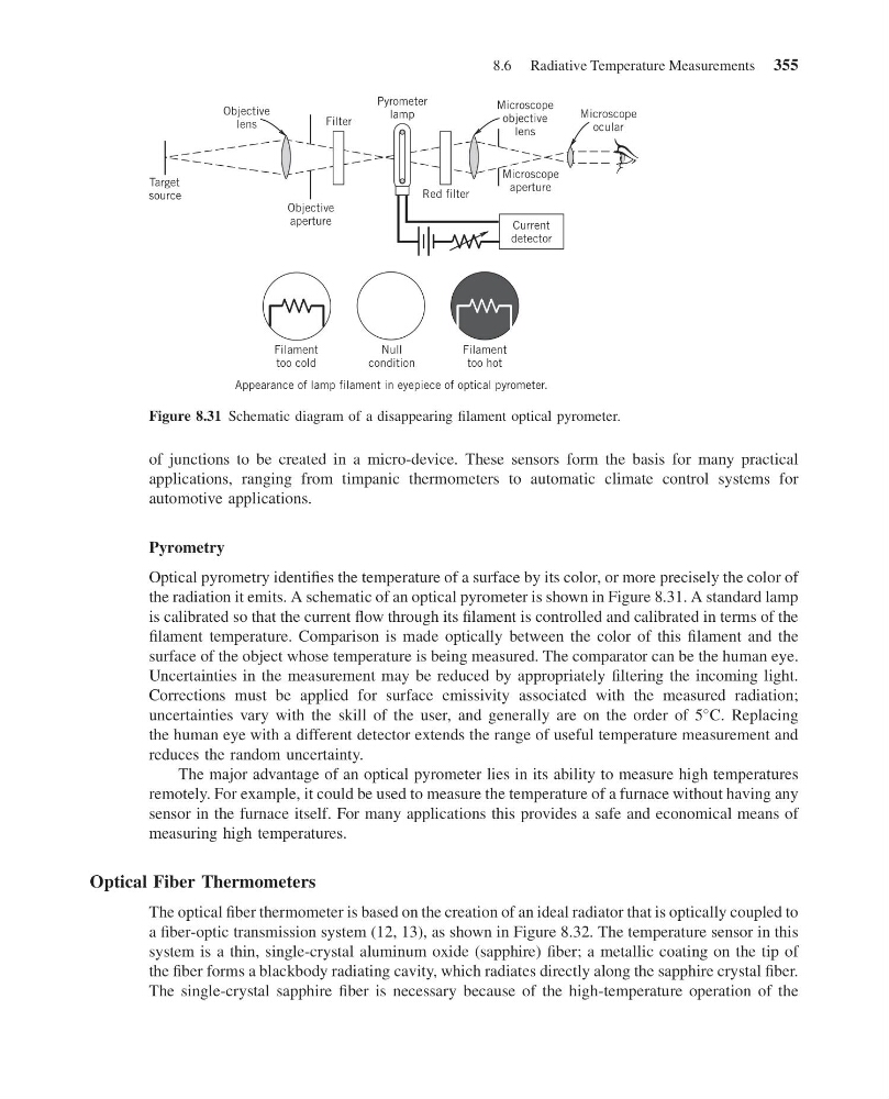
the radiation it emits. A schematic of an optical pyrometer is shown in Figure 8.31. A standard lamp
is calibrated so that the current flow through its filament is controlled and calibrated in terms of the
filament temperature. Comparison is made optically between the color of this filament and the
surface of the object whose temperature is being measured. The comparator can be the human eye.
Uncertainties in the measurement may be reduced by appropriately filtering the incoming light.
Corrections must be applied for surface emissivity associated with the measured radiation;
uncertainties vary with the skill of the user, and generally are on the order of 5
C. Replacing
the human eye with a different detector extends the range of useful temperature measurement and
reduces the random uncertainty.
The major advantage of an optical pyrometer lies in its ability to measure high temperatures
remotely. For example, it could be used to measure the temperature of a furnace without having any
sensor in the furnace itself. For many applications this provides a safe and economical means of
measuring high temperatures.
Optical Fiber Thermometers
The optical fiber thermometer is based on the creation of an ideal radiator that is optically coupled to
a fiber-optic transmission system (12, 13), as shown in Figure 8.32. The temperature sensor in this
system is a thin, single-crystal aluminum oxide (sapphire) fiber; a metallic coating on the tip of
the fiber forms a blackbody radiating cavity, which radiates directly along the sapphire crystal fiber.
The single-crystal sapphire fiber is necessary because of the high-temperature operation of the
Current
detector
Red filter
Filter
Objective
aperture
Target
source
Objective
lens
Pyrometer
lamp
Microscope
objective
lens
Microscope
ocular
Microscope
aperture
Filament
too hot
Null
condition
Appearance of lamp filament in eyepiece of optical pyrometer.
Filament
too cold
Figure 8.31 Schematic diagram of a disappearing filament optical pyrometer.
8.6 Radiative Temperature Measurements 355
14:54:1 Page 355
of junctions to be created in a micro-device. These sensors form the basis for many practical
applications, ranging from timpanic thermometers to automatic climate control systems for
automotive applications.
Pyrometry
Optical pyrometry identifies the temperature of a surface by its color, or more precisely the color of
the radiation it emits. A schematic of an optical pyrometer is shown in Figure 8.31. A standard lamp
is calibrated so that the current flow through its filament is controlled and calibrated in terms of the
filament temperature. Comparison is made optically between the color of this filament and the
surface of the object whose temperature is being measured. The comparator can be the human eye.
Uncertainties in the measurement may be reduced by appropriately filtering the incoming light.
Corrections must be applied for surface emissivity associated with the measured radiation;
uncertainties vary with the skill of the user, and generally are on the order of 5
C. Replacing
the human eye with a different detector extends the range of useful temperature measurement and
reduces the random uncertainty.
The major advantage of an optical pyrometer lies in its ability to measure high temperatures
remotely. For example, it could be used to measure the temperature of a furnace without having any
sensor in the furnace itself. For many applications this provides a safe and economical means of
measuring high temperatures.
Optical Fiber Thermometers
The optical fiber thermometer is based on the creation of an ideal radiator that is optically coupled to
a fiber-optic transmission system (12, 13), as shown in Figure 8.32. The temperature sensor in this
system is a thin, single-crystal aluminum oxide (sapphire) fiber; a metallic coating on the tip of
the fiber forms a blackbody radiating cavity, which radiates directly along the sapphire crystal fiber.
The single-crystal sapphire fiber is necessary because of the high-temperature operation of the
Current
detector
Red filter
Filter
Objective
aperture
Target
source
Objective
lens
Pyrometer
lamp
Microscope
objective
lens
Microscope
ocular
Microscope
aperture
Filament
too hot
Null
condition
Appearance of lamp filament in eyepiece of optical pyrometer.
Filament
too cold
Figure 8.31 Schematic diagram of a disappearing filament optical pyrometer.
8.6 Radiative Temperature Measurements 355